Autodesk Fabrication products support BIF (Batch Import File) forma. This format is designed to assist in the automatic creation of parts for jobs. These are designed for profiling and nesting, and are not 3D parametric shapes. A BIF file is a text file in ASCII text file format that can contain definitions of simple shapes, such as a rectangle or square, or it can contain links to other external files, such as DSTV structural steel parts, DXF files, or NC files.
The file is saved with a BIF file extension and can contain any number of lines. Each line in the file describes one import operation. The fields in the line are as follows:
Format, Item Name, Material, Thickness, Quantity, Import File, Length, Width
Fields that are not required for a particular format may be left blank.
Below is an example of a typical BIF file:
DXF,dxf1,Galvanised,0.6,,c:\map-software\cam\dxf\elephant.dxf
RECT,rect1,Galvanised,0.6,10,,600,400
Burny,burny1,Mild Steel,1.0,,c:\map-software\cam\cnc\10007602.B3
Burny,burny1,Galvanised,0.6,,c:\cam\cnc\00020.B3
DSTV,dstv1,,,12,C:\Customer Files\Customer1\NC1\187.nc1
DSTV,dstv2,,,34,C:\Customer Files\Customer1\NC1\188.nc1
DSTV,dstv3,,,,C:\Customer Files\Customer1\NC1\189.nc1
DSTV,dstv4,,,,C:\Customer Files\Customer1\NC1\190.nc1
DSTV,dstv5,,,,C:\Customer Files\Customer1\NC1\191.nc1
DSTV,dstv6,,,,C:\Customer Files\Customer1\192.nc1
DXF,dxf2,Galvanised,0.6,,c:\cam\dxf\grommit.dxf
The first line is defined as follows:
DXF = Format of the file. In this case, it is a DXF file from CAD. Supported file formats are:
- DXF: AutoDesk Drawing Exchange Format.
- NC files: Any valid NC file that is supported. Note that the Installed Machine that is associated with the NC file must be present in the machine setup.
- DSTV: Xsteel file format with an nc1 file extension.
- RECT: Built in simple rectangular shape generator.
dxf1: This is the Item Name that will be assigned to the Item once imported into the job. This can be any description.
Galvanised: This is the Material to be used for the item. This material must exist in the database.
0.6: This is the Thickness or gauge of the Material previously specified.
,,: This is the Quantity field. If left as a pair of commas, it will place one part in the job. Otherwise state a value. c:\map-software\cam\dxf\elephant.dxf = This is the path and filename of the previously specified format file that is to be imported into the job. Network and mapped drives can also be used in this line.
The Length and Width fields are only used when using the Format RECT and define the length and width of the rectangle.
Any field that is to be left blank, such as the Material field, when importing a DSTV file as that will be brought in by the file itself, is to be left as a pair of commas. The BIF file is then brought into the job from the File > Import > Batch Import menu, or it can be automatically entered and processed using Batch Mode.
It is possible to run two separate CAMduct applications on the same PC: one for using normal manufacturing takeoff, and the other for placing into a Batch Mode.
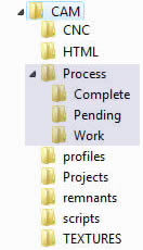
Batch Mode is run minimized and is continuously processing/scanning in the background for files to be processed. In order for it to do this, a folder must be created in the CAM folder called Process. CAMduct then creates 3 sub folders within this folder called Complete, Pending, and Work, shown as below.
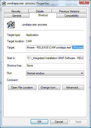
A shortcut to the application exe file needs to be created, and a switch is required in the Target at the end of the path, as shown below. Creating the shortcut to the software (i.e umdiapp) and placing /Process at the end of the target enables Batch Mode when the shortcut is run.
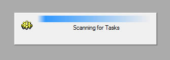
This shortcut can be used to start the software in Batch Mode, and alternatively placed in the Windows Start-up folder to run each time the PC is turned on. The application should display Scanning for Tasks if the configuration has been successful.
Any files placed in the Pending folder are automatically dealt with by the Batch Mode application.
The program can also be started in Batch Mode from the New Job Wizard.