On the Machine Editor dialog, the NC Settings tab contains options that directly affect the final NC data file output.
To access and edit these settings:
- Click File
 Setup
Setup
 Installed Machines, or select Installed Machines from the Utility Bar.
- Select the machine to edit or setup.
- Double click the machine name or press the
 button.
- Click the NC Settings tab from the Machine Editor dialog.

The following settings are available on this dialog.
Move Nest to Home Point: This option will adjust the position of the nest so that the material used first is the material closest to the home point.
Apply Kerf: Enable this option if you wish the Write NC command to compensate for Kerf instead of the machine controller.
Kerf Tight Gaps: This option will apply kerf to small spaces. Normally the cutter will only proceed as far as it can without going over a line, as shown in Fig 1.

With Kerf Tight Gaps enabled, the cutter will go all the way to the bottom of the gap, as shown in Fig 2.

Keep Current Nest Part Order: If enabled, the NC writer will not change the cut order.
Part Ordering: This option determines the order in which the parts will be cut. If the Keep Current Nest Part Order option is enabled, this option will not be available. Setting this option will ensure that the machine torch will not move back towards the already cut section of the sheet. Therefore cut parts can be taken off the table before the machine has finished. The methods that can be selected are Label Application (i.e. keep the same cutting order as printed with the part labels), Allow Heat Dissipation and Shortest Path (where the controller will make the decisions based on its own internal settings).
Along Rail Axis / Along Beam Axis: This determines which axis is to be cleared first.
Priority: These settings determine in what order the machine will use the tools to manufacture the parts.
Part by Part: This option will use multiple tools on the same part before moving on to the next part.
Tool by Tool: On multiple tool machines, determines the order that tools are used in. Highlight a tool by clicking it, then use Move Up / Move Down arrows to change the tool order.
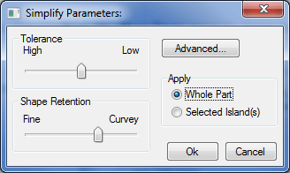
Simplify Islands: Simplify takes the drawing and reduces its level of complexity so that when the NC is written for it, there are less instructions to download to the cutting machine. It is particularly useful on drawings containing True Type Text and ellipses, and on scanned in drawings. Click on Setup and this Simply Parameters dialog displays.

Tolerance High/Low: This slider bar determines whether the simplify command uses High tolerance levels for a more accurate representation or you can choose Low to lower the tolerance levels.
Shape Retention Fine/Curvey: This slider bar determines whether the simplify command uses Fine shape retention levels for a more accurate representation of the part or you can choose Curvey to lower the shape retention levels.
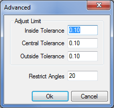
Apply Whole Part / Selected Islands: This determines whether the whole drawing or just a selected region is simplified. Clicking on the Advanced button displays the following dialog.

Inside / Central / Outside Tolerance: These figures specify at what point lines are merged to form a single line.
Restrict Angles: This sets the angle that two consecutive lines must fall between before they will be considered for merging into a single line.