These steps describe how to create a new connector. This example uses a round female threaded connector that is defined according to the parameters included in the GRC_M_FPT-125# (B1.20.1&B16.15) specification.
To create a new connector:
- On the Database dialog, click Fittings
 Connectors to display the Connectors dialog in the right pane.
- At the top of the dialog, for Library, specify Round.
- Click the New button
 to display the Connector "Untitled" dialog.
- In the Name field, specify a name for this new connector.
For this example, for the connector name, type in GRC_M_FPT-125# (B1.20.1&B16.15), and then click Close.
See Connector Names and Abbreviations for descriptions of some typical connector naming abbreviations and conventions.
- Right-click on the new connector and click Change Group.
- Specify a group name and click OK. For this example, type in “Autodesk” for the group name.
The connector should now be located under the specified group. The next step is to define the connector’s geometry.
-
Right-click on the connector and click Edit, and then click the Breakpoints button at the bottom of the Connector dialog.
The following dialog displays.

From the manufacturer's literature, identify the parameters that are required to define the breakpoints geometry for this connector. The following diagram is an example. This diagram illustrates the parameters associated with a female threaded connector that is defined in the specification, and is also named, named GRC_M_FPT-125# (B1.20.1&B16.15).
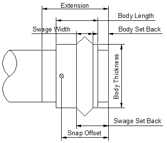
From the manufacture's data, the parameters associated with this female threaded connector are listed and described below.
(A) Diameter - The Diameter should include all sizes of this item that could use this connector.
(B) Extension - Defines the connector length within the item body.

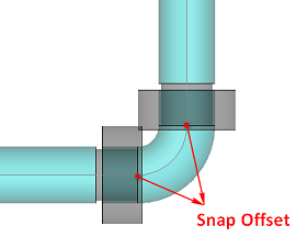
(C) Snap Offset - This defines the distance, or depth, that one connector inserts into the other connector.
(D) Body Thickness - When the Extension Includes Diameter parameter is set to Yes, then the Body Thickness parameter includes the Diameter.

When the Extension Includes Diameter parameter is set to No, then the Body Thickness parameter excludes the Diameter.

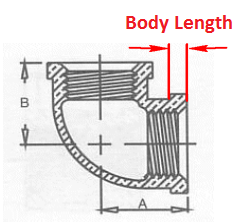
(E) Body Length - This defines the length of the connector body.
Other parameters include:
(F) Body Set Back
(G) Swage Set Back
(H) Swage Length
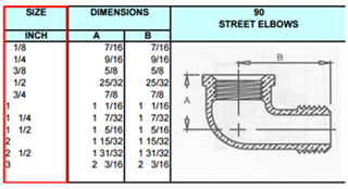
The female threaded connector used in this example uses the specifications that are listed in the following table, which is from the manufacturer’s catalog. In this example below, the ASME B16.15 specification defines the connector body geometry, and the ASME B1.20.1 specification defines the connector thread geometry.Info from Manufacturer's Specifications

- Create an external spreadsheet table that contains the appropriate parameter data for the connector.
Note: The order of the columns in the external spreadsheet table should be the same as the order of the columns in the Connector Breakpoints table in the Autodesk Fabrication product.
- Copy and paste the source data, from the manufacturer's data, that defines the connector geometry into the external spreadsheet table.
Ensure the parameter values (A~H columns) are in the appropriate order.
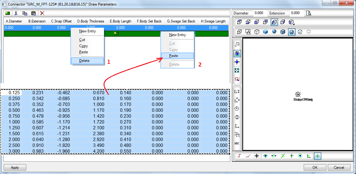
- Now copy the properly formatted data from the external spreadsheet and paste it in to the Connector GRC_M_FPT-125# (B1.20.1&B16.15) Draw Parameters dialog in the Autodesk Fabrication product.
- In the Connector GRC_M_FPT-125# (B1.20.1&B16.15) Draw Parameters dialog, right-click on the top row, containing the 0.000 data, and delete this line, as shown in the Delete drop-down list (1) shown below.
-
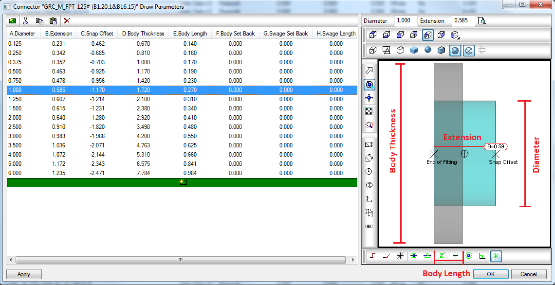
Click the parameter, select left view and transparent, and the connector geometry displays in the right pane, as shown below.
Now that the new connector is created, and the specific geometry parameters of the connector have been added, the next step is to set manufacturing and other properties.
- To specify the Manufacturing properties of the new connector, on the Database dialog
Fittings
Connectors dialog, click on the Manufacturing button
 .
.
- In the dialog, right-click on the new connector and click Edit.
- On the Connector dialog, set the Type to Pipework, and then click Close.
- To set the Costing properties, click on the Costing button
 .
.
- Right-click on the connector and click Edit.
- For Material, specify the connector material from the drop-down list. For this example, use the GRC_125#-ASME B material in the Mechanical Fittings, and then click Close.
- To set the Drawing properties, click on the Drawing button
 , then right-click on the connector, and click Edit.
- Set the following parameters:
-
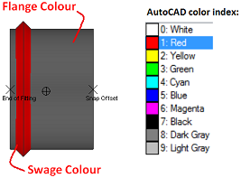
Flange Colour: Specifies the color of the connector body. Specify a number to display the associated color, as shown in the AutoCAD color index table below.
- Swage Colour: Specifies the color of the swage. Specify a number to display the associated color, as shown in the AutoCAD color index table below.
-
Connectivity: Specify the connectivity based on the connection type. Refer to the table below. If the connector is not designed to be connected, leave this blank.
Connection Type Connectivity MPT/FPT
Threaded Flange/Wafer/Lug
Flange Closet Flange
Closet Flange Solder/Plain End/Hub/Spigot/FTG/Fusion
Tube & Fittings Grooved
Grooved Butt Welded/Socket Welded
Welded Lapped/Stub End
Stub End Hose
Hose - End Type: Specifies the connector gender or type. Connectors with the same connectivity and matched end types will be joined automatically when users are laying out a Design Line. For this example, specify Female.
-
End Draw Type: Specifies the connector shape.
- Extension includes Diameter: This option can be set as Yes or No, and affects the Body Thickness parameter in Breakpoints.
-
- Set the ownership property by right-clicking on the connector and clicking Owner Information. On the Database Owner Information dialog, set these parameters as needed for your projects.
- Owner: When User Defined is specified as the default, this connector can be edited by everyone.
- Version: Specify the version number or click the button to set version.
- Enter Reason for Change: Specify the reason this connector is being updated.
- History: Clicking this button displays the history of versions for this connector, and their associated information.
- Click OK to close the Database Owner Information dialog.
Define Connector Geometry
Set Manufacturing and Other Properties
At this point, the connector is created.