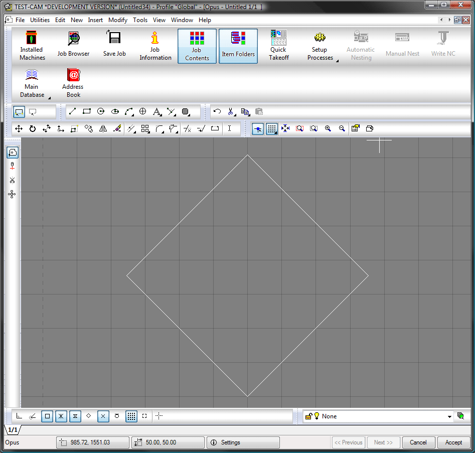
Opus is the CAD drawing tool within Autodesk Fabrication CAMduct. While there are some similarities between Opus and the 3D Viewer window, Opus is primarily used for creating and editing flat pattern developments.
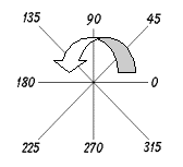
The diagram below shows how angles are determined within Opus. This diagram is useful for understanding how Opus assigns correct angle to lines and shapes.
How to draw with the Absolute / Relative drawing system
The main point of absolute positioning is that the 0,0 position never moves. In contract, the main point of relative positioning is that the 0,0 position always moves to the active point or selected point within the drawing.
Below is an example of how this drawing system operates. The drawing is simply a rectangular shape.
- Do one of the following:
- Click New
 Lines
Lines
- Click the Line icon

- At the command line, type Line, and press Enter.
- Click New
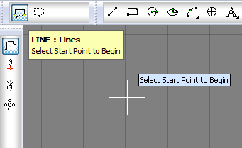
- The following prompt displays on the drawing area: LINE: Lines Select Start Point to Begin.
- By default all points, except the first point, are considered to be relative to the last active point.
- Click anywhere on the screen with the cursor, using the left-mouse button. The line becomes anchored to that point.
- Type 500,0 and press Enter. A horizontal line is drawn in the same fashion as with absolute mode.
- Type 0,500 and press Enter. A vertical line displays.
- Type -500,0and press Enter. A horizontal line displays, giving a reversed ' c' pattern. The minus sign informs Opus to move the line backwards from the working point.
- Type C and press Enter. The rectangle finishes, and the command ends. Pressing the C causes the line to connect from its current position to the start position, and is useful when finishing a part.
The diagram below shows how the negative sign is used when working co-ordinates out:

To Draw in Absolute Mode
When you start drawing lines the first point is always absolute and then auto-relative for all subsequent points. You can force it to use absolute co-ordinates if you use the @ symbol as a prefix.
- Do one of the following:
- Click New
Lines
- Click the Line icon
- At the command line, type Line, and press Enter.
- Click New
- As previously described, the following prompt displays: LINE: Lines Select Start Point to Begin .
- Type @0,0 and press Enter. The line becomes anchored to the 0,0 point
- The command line changes to Select Next Point. type @500,0 and press Enter. A horizontal line is now drawn.
- Type @500,500 and press Enter. A vertical line displays.
- Type @0,500 and press Enter. A horizontal line displays, giving a reversed ' c' pattern.
- Type C and press Enter. The rectangle finishes and the command ends. Pressing the C caused the line to connect from its current position to the start position, and is useful when finishing a part.
To draw using the direct Line Input (Ortho) method
At times, some profiled parts are simple straight line developments, so to aid in the drawing of these parts it is recommended to make use of the following drawing technique:
- Do one of the following:
- Click New
Lines
- Click the Line icon
- At the command line, type Line, and press Enter.
- Click New
- As previously described, the following prompt displays: LINE: Lines Select Start Point to Begin .
- Click anywhere on the screen with the cursor using the left-mouse button.
- Press the F8 key enabling Orthographical mode (straight lines) and move the cursor to the right.
- Type 500 and press Enter, and then move the cursor to the top of the screen
- Type 500 and press Enter, and then move the cursor to the left.
- Type 500 and press Enter
- Type C and press Enter. The rectangle will be completed.
How to draw lines at angles
To draw an angled line, it is very similar to the quick method described above, the only difference being that the angle is incorporated into the direct line method. For example, to draw a 500mm x 500mm square, rotated at an angle of 45 degrees:
- Do one of the following:
- Click New
Lines
- Click the Line icon
- At the command line, type Line, and press Enter.
- Click New
- As previously described, the following prompt displays: LINE: Lines Select Start Point to Begin .
- Click anywhere on the screen with the cursor using the left-mouse button.
- Type 500<45 and press Enter.
Note: Placing the < symbol in between the first and second set of figures determines that the first figure (in this case 500) will be a length, and the second figure (in this case 45) will be an angle. Therefore, 500<45 draws a line 500mm long at 45 degrees.
- Type 500<135 and press Enter.
- Type 500<225 and press Enter.
- Type C and press Enter. The rectangle is complete.