There are a range of drainage services which include specific tools to aid in the construction of these systems. This topic is designed to show how the service and related tools are used in practice.
Pipe work with Gradient
Adding the Main Run
- From the Service Selector drop-down menu, select Soil & Waste Drainage from the Waste Disposal & Drainage group.

- Select the Cast Tab from the Service Button Template.
- Click the Cast Iron Pipe Icon to display the Add Items dialog.

- Select 200 from the Description drop-down list.
- Click OK.
- Select a position on the drawing to start the Main run - this will prompt the Fix Relative dialog.
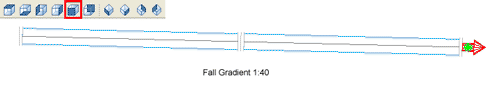
- In this example, the Fall Gradient will be specified as 1:40 - type 40 in the Fall gradient box.
- Click OK to add the first pipe section.
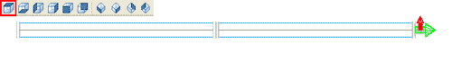
- Click the Cast Iron Pipe button again to add another section. The following displays:
Adding the Branch Run
- Revert back to the Plan View.
- Click the Cast Iron Pipe button to display the Add Items dialog.
- Select 150 from the Description drop-down list.
- Click OK.
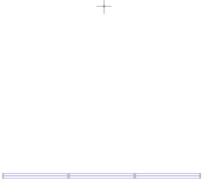
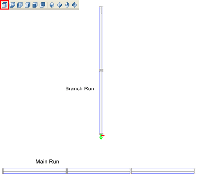
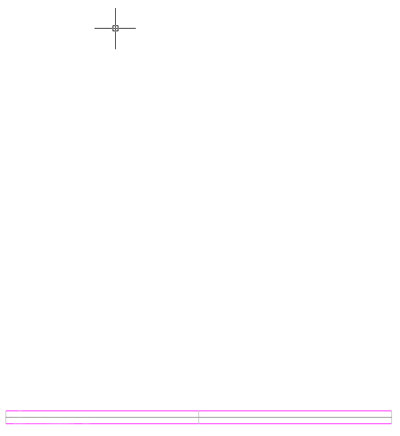
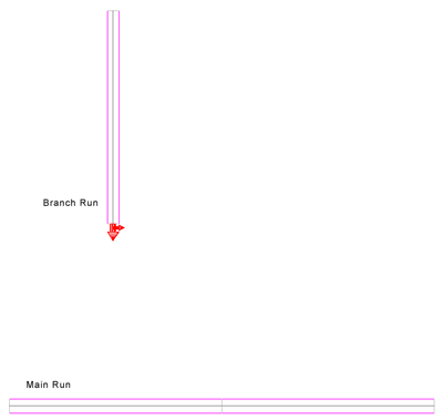
- Select a position on the drawing relative to the Main Run as show below. This displays the Fix Relative dialog.
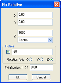
- Check the Rotate option and add a value of -90 (minus 90). Leave the default Rotation Axis set to Z.
- Enter a value of 40 in the Fall Gradient box.
- Click OK. The first section of the Branch run should now have been added to the drawing.
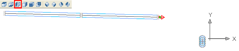
- Click the Cast Iron Pipe button again to add another section. The following displays:
- Select the Left View and move Branch run up in the Y plane 1000.
- Switch back to the Plan View.
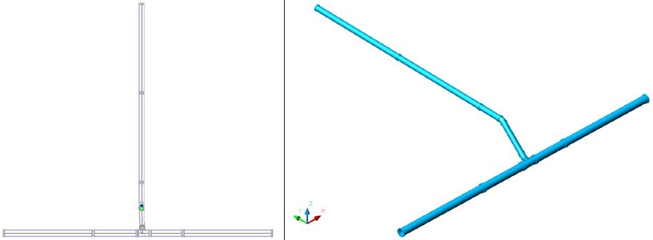
- Right click the 88-Curved-Branch and select Drop into Fall.

- The command line prompts : Select End of Branch run. As shown, select the End of the Branch run.

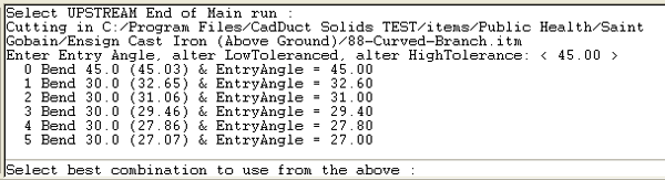
- The command line prompts: Select UPSTREAM End of Main run. As shown, select UPSTREAM End of Main run. Note: UPSTREAM End of Main run is defined by the nearest connector end of the section, left or right of center.

- Select 200x150 from the Description drop-down list.
- Click OK.

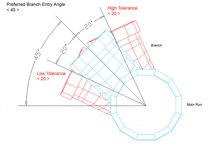
- The command line prompts: Enter Entry Angle, alter LowTolerance, alter HighTolerance: < 45.00 >. Note: The Preferred Branch Entry Angle currently selected is stated in brackets, in this case < 45 > (45 degrees). The LowTolerance & HighTolerance options may be selected and adjusted as necessary by typing LT or HT at the command line when prompted. In the example shown below, the Low & High Tolerance values are set at <20> (20 degrees). CADmep will try to provide a solution for the entered angle and will also try angles between entered angle-LT and entered Angle +HT; i.e. rotation angles for the swept branch of between 25 to 65 degrees.
- Click Enter to accept the default entry angle of < 45 >. The command line displays a list of Entry Angles based on the High/Low Tolerance values selected.
- For this exercise, enter 0 at the command line, then press Enter to select the Bend 45.0 (45.03) & EntryAngle = 45 option.
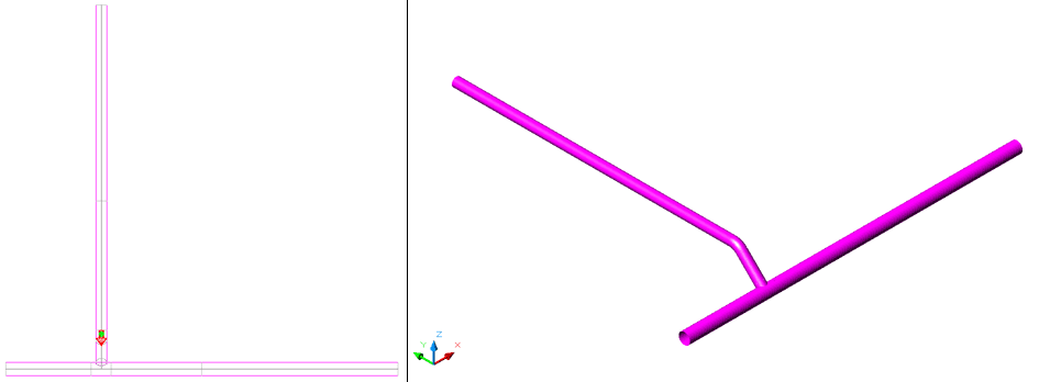
The following result should be obtained:
Pipe work without Gradient
Procedure
Adding the Main Run
- From the Service Selector drop-down menu, select LTHW-CT from the Space Heating group.

- Select the Pipework tab from the Service Button Template.
- Click the button to display the Add Items dialog.

- Select 400 from the Description drop-down list.
- Click OK.
- Select a position on the drawing to start the Main run - this will prompt the Fix Relative dialog.
- Click OK to add the first pipe section.
- Click the Cast Iron Pipe button again to add another section. The following displays:
Adding the Branch Run
- Click the Cast Iron Pipe button to display the Add Items dialog.
- Select 300 from the Description drop-down list.
- Click OK.
- Select a position on the drawing relative to the Main Run, as show below.
- At the Fix Relative dialog, enter the following values.
- Click OK. A section of Branch run should now have been added to the drawing. The following displays:

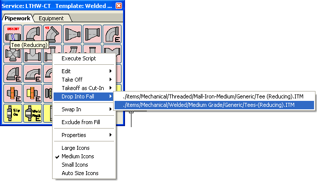
- Right click the Tee (Reducing) and select Drop into Fall (select the second item form the list).
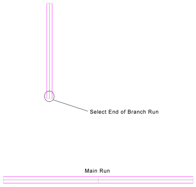
- The command line prompts : Select End of Branch run. As shown, select the End of the Branch run.
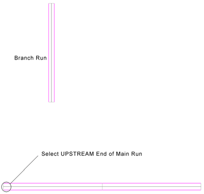
- The command line prompts: Select UPSTREAM End of Main run. As shown, select UPSTREAM End of Main run. Note: UPSTREAM End of Main run is defined by the nearest connector end of the section, left or right of center.
- Select 400x300 from the Description drop-down list.
- Click OK.

- The command line prompts: Enter Entry Angle, alter LowTolerance, alter HighTolerance: < 45.00 >. Note: Enter the preferred Entry Angle - Please refer to the Note attached to Pipe work with Gradient - Step 18 .
- Select the Return key for the default entry angle of <45>. The command line should report a list of Entry Angles based on the High/Low Tolerance values selected.
- In this example, you are prompted with one option, as follows:

- Press Enter again to accept the option.
The following result should be obtained as per the images below: