The Takeoff Settings dialog is available from within the pattern Takeoff dialog.
- In the pattern Takeoff dialog view window:
- right-click
 Settings
- click the Settings button
 in the Takeoff toolbar, typically located along the left side of the view window
- right-click
The Takeoff Settings dialog has 8 tabs that control a variety of settings within the Takeoff dialog. These are described below.
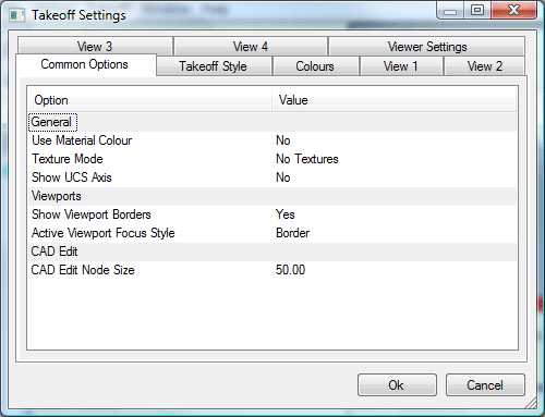
Common Options Tab
The Common Options tab sets the global options for the Takeoff views. In the General Section the user can set:
Use Material Color: This drop-down specifies Yes or No as to whether the Material Color, setup in the Materials Database (Main Database
Materials) is used in the View Windows.
Texture Mode: Textures are setup in the Pattern Database
Facings dialog. This dialog lets you specify whether Textures are displayed, Textures displayed with Material Color, or No Textures are used. Textures can be applied or turned off in each of the Views using the Texture icon in the Toolbar
 .
.
Show UCS Axis: Select Yes or No to display the USC axis in the View window.
In the Viewports Section you can set:
Show Viewport Borders: This draws a border around the individual viewports, or turn them off if set to No.
Active Viewport Focus Style: If set to None, the active window is not highlighted. If set to Border, the active window has a bold border round it.
In the CAD Edit Section you can set:
CAD Edit Node Size: This is used when Importing a 3D model and is set to determine the size of the Attacher Arrow when used in CAD mode.
The next tab is the Takeoff Style tab.
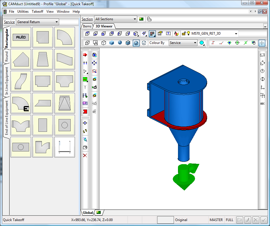
Takeoff Style Tab
This tab allows lets you select and modify:
Font: This is the font that is used for the annotation and dimensioning in the Takeoff dialog. Any installed True Type font can be used.
Presentation: This is the size of the font that will be used in the Takeoff window.
Decimal Places: This displays dimensions to the number of decimal places determined in this box, if the Suppress zeroes check box is used then the zeroes will be stripped out if a whole number is entered, Instead of displaying 450.00 it will display 450 in the annotation
Rounding: The software can round up, down or round to nearest number. So if 100.75 is entered, and 1 Decimal Place is selected, it will display 100.8 with Round Up , 100.7 with Round Down and 100.8 with Round Nearest , in the annotation.
Shape: Specifies a shape to encapsulate the dimension annotation. The choices are:
Circle
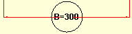
Oval
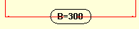
Rectangular
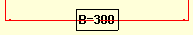
None
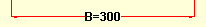
Margin: This slider controls the distance that the shape encapsulates the text.
Leader: Specifies a leader type for the dimension lines. The choices are:
None
Filled
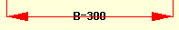
No Leader
Arrow Size: This determines the size of the Arrow Head used in a Leader. This ranges from 1 to 8, with 1 being the largest and 8 being the smallest.
Colors Tab
The next tab is the Colors tab.
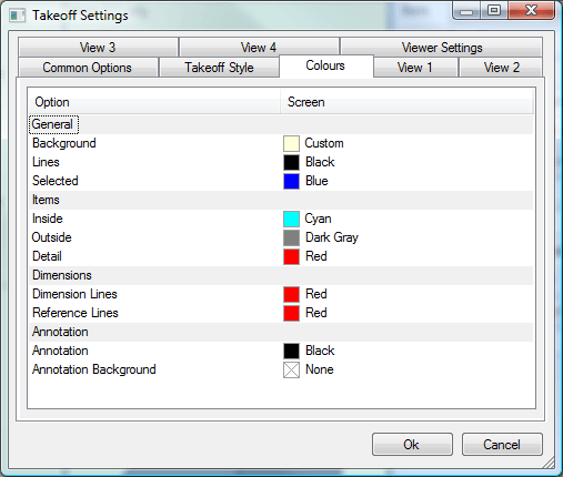
The Colors tab lets you customize the look of the viewports in the Takeoff dialog. This tab is organized into 4 sections: General, Items, Dimensions, and Annotation.
General: Specifies the colors that will be displayed for background, lines and selection mode.
Background: To change the color of the background in the Viewports click on the small color box to display the color selector pulldown.
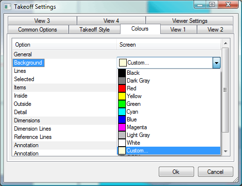
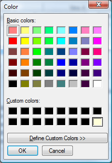
The color selected will be displayed in all the viewports as the background. Selecting Custom displays the Windows Color Picker to further customise the color chosen.
All colors are selected (specified) the same way.
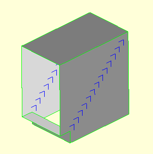
Lines: The colors are changed the same way as the background, but will affect the lines that draw the duct in the Viewports The following image shows an example of how an item would display in (all viewports in) the Takeoff window when the lines are set to a bright green color.
Selected: This is the Line color that is displayed in the 3D Viewer when in CAD Mode and an item is selected in the viewport.
Items Section
Inside: This is the color that will be displayed on the inside of the item in the Viewport.
Outside: This is the color that will be displayed on the outside of the item in the Viewport.
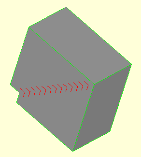
Detail: This is the color that details on the item, such as Air Turns, will be displayed in the Viewport. Example below shows Air Turns set to a dark blue color.
Dimensions
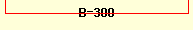
Dimension Lines: Specifies the color that Dimension Lines are displayed in Viewports.
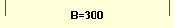
Reference Lines: Specifies the color that the Reference Lines that lead from the Dimensions to the item are displayed in Viewports.
Annotation
Annotation: Specifies the color that Text and Numerals are displayed in Viewports.
Annotation Background: Specifies the color that will be used as the background of the Text if a Shape is used in the Takeoff Style.
Annotation can also be applied or switched off in each of the Views by using the Annotation icon
 in the Toolbar.
The next tab is the Viewer Settings tab.
Viewer Settings Tab
This tab controls certain display settings for the 3D Viewer in Quick Takeoff. There are, however, a couple of display settings that affect the Views in Normal Takeoff. These are:
Graduated Background: When this option is selected, this displays a background that is dark at the bottom, and gets lighter as it nears the top. This is applied to the specified Background Color selected in the Colors tab.
Zoom Factor: Specifies how far the item zooms in or out of the Viewport when using the mouse scroll wheel. You can specify a factor from 0.1 to 2, with 2 being the fastest.
The next tabs are the View # Tabs.
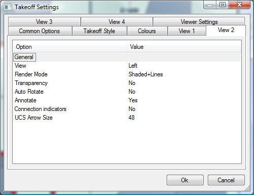
The options available for each view are as follows:
View #: Specifies the pattern view that is displayed in this view window. The Views available are:
- Plan
- Bottom
- Front
- Back
- Left
- Right
- Isometric
These can also be selected by using the View icon
 in the Toolbar.
Render Mode: Specifies the Draw Type displayed in the view window. The options available are:
- Lines
- Shaded
- Shaded + Lines
These can also be selected using the Render icon in the Toolbar.
Transparency: This applies transparency to the View, and works the same as the Transparency available in the Render Mode.
Auto Rotate: This causes the view to spin automatically.
Annotate: Applies Annotation to the view.
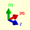
Connection Indicators: This will display the Connector Indicators in the view, these are represented by a Red Circle and a Red Cone.
UCS Arrow Size: Allows the user to modify the size of the UCS indicator, if displayed.
The four views serve two purposes. They give an impression of what the fitting will look like when cut and fully formed, and they also act as a guide for determining what particular dimensions refer to.
-
Click Redraw or pressF7 to update the four views to reflect changes made in the Data Input section.
-
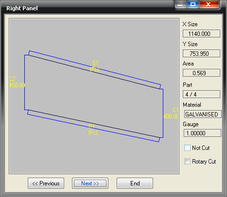
Click on the Develop button to bring up a view of the parts in their two-dimensional profiled form. As below.
-
This Development view allows the user to cycle through the separate developments of the fitting. The view will display the original extents of the pattern (black) and any allowances that have been added on (light blue). Development lines (green) and inner cuts (red) where applicable are also displayed.
-
The identifiers for connectors and seams are also shown (Cx / Sx).
-
The X Size and Y Size fields displays the blank size of the development.
-
The Area field displays, in mm/sq the actual area of the developed part.
-
The Part field displays the amount of developed parts within the fitting and which one is currently being viewed. It is possible to view all of the developments within a fitting by clicking on the Next and Previous buttons. Click End to return to the Pattern Takeoff dialog.
-
The Material and Gauge fields displays the selected material and gauge for the fitting.
-
Enabling the Not Cut option allows the user to disable the cutting of individual developments within a fitting.
-
Rotary Cut is used when Rotary Nesting has been applied and is only applicable for Rotary Cutting machines.