This topic describes the method for processing DXF files, which include the geometry of one or more parts, tooling information on each part, such as cutting, drilling, marking, etc., attribute information on each part, and part number, material, quantity, and so on.
AutoCAD Layering
The drawing containing the parts to be processed is often complex and contains many layers. The parts to be processed should therefore be placed on nominated layers.
Example:
- Parts to be processed with the cutting tool on layer: cutting
- Parts to be processed with the marking tool on layer: marking
- Parts to be processed with the drilling tool on layer: drill
- Text containing attribute information on layers: attributes
The following example uses AutoCAD 2008. Your CAD software may be different, but the principles are the same.
- In AutoCAD, open a drawing, then click on Format
 Layer.
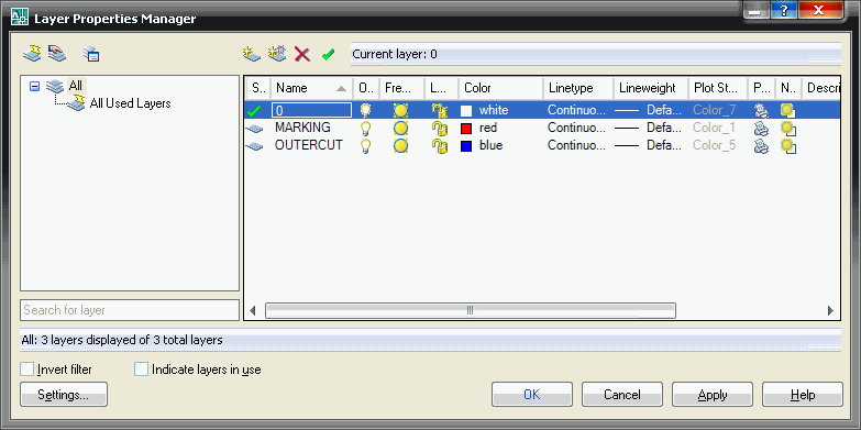
 - In the Layer Properties Manager, click New.
- In the details section, enter Cutting as the name for this layer and change the color to Blue.
- Click New again, but this time enter Marking for the name, and Red as the color.
- Click OK to return to the drawing, and click on the Properties icon (the first left below) to display the properties for the drawing.
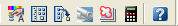
- Select an object to change its layer, and in the Properties pallet, change the layer by clicking the Down Arrow and select the Cutting layer.
- Press the Esc key, then select a different object and change its layer to Marking. Notice how the objects change color to match the different layer colors.
- Click on the X in the Properties pallet to close it.
- When you have finished editing the drawing, click on File Save As.
- In the files of type section, click the down arrow and select AutoCAD DXF (*.DXF).
- Name the drawing, then click Save.
Profiler Database: Profiler is the module responsible for processing imported parts. If the DXF files contains text, tooling or attribute information contained in layers, the layer mapping must be defined in Files Setup Profiler Database.
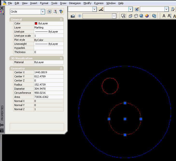
Profiler Options
- Text contained in DXF files may be ignored, processed or set as display only.
- Set text islands to process if the text is to be written on the part by the laser, marker or printing tool.
- Set to process if the text is to be converted into attributes.
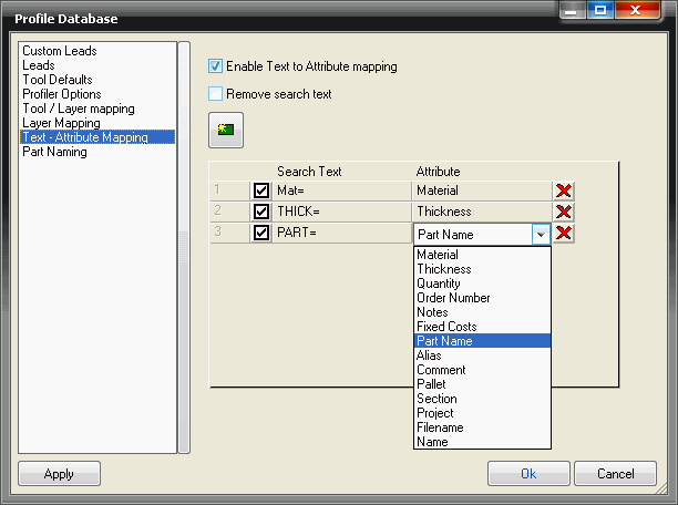
Profiler: Text Attribute Mapping
- Attributes can be contained in text streams, one per attribute.
- The start of text must lie within the rectangle bounding the geometry.
- The search text must be exact and is case sensitive.
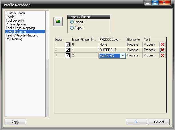
Layer Mapping: Allows mapping between AutoCAD layers and other software application layers. In the example below:
- The imported layer cutting will be mapped to the software layer Cutting.
- The imported layer hole will be mapped to the software layer Drilling.
The software layer names are arbitrary, and at this stage, do not imply that the cutting tool or drilling tool will be assigned. Layer mapping must be used in conjunction with Tool / Layer Mapping.
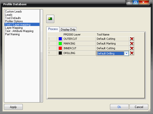
Tool Layer Mapping
- The Cutting layer has been assigned the default cutting tool; i.e. a laser; plasma; oxy-fuel.
- The Marking layer has been assigned the default marking tool i.e. Scribe, Laser Marker.
- The Drilling tool has been assigned the default drilling tool i.e. center punch, drill.
- If the drilling tool is assigned to a layer only full circle entities will be processed on that layer and assigned to the drill tool.
Example DXF Import: Parts can be imported directly into an open job or alternatively they can be imported into item folders for permanent storage and future use.
Import to Item Folders
- From Utilities Item Folders, select or create the required folder.
- Right-click in the folder and select New Import.
Import into a Job
- Select File Import Items
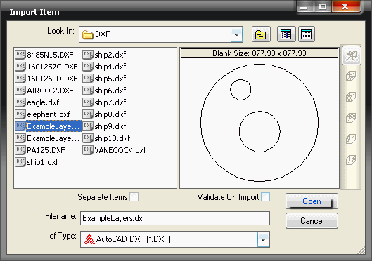
- "of Type" should be set to DXF.
- Browse to the required folder.
- Separate items should be selected if the DXF file contains multiple parts.
- Click on Open.
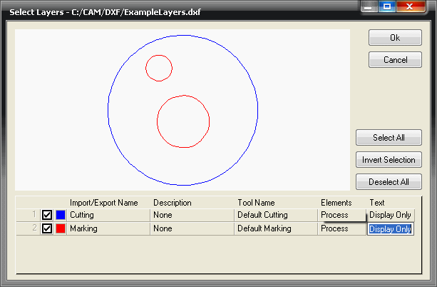
- If the AutoCAD filter has been applied before exporting the DXF file, it will not contain any irrelevant layers or drawing elements.
- However, unwanted layers can be switched off here, if necessary.
- The part will be processed and added to either the item folder or the job.
- To verify the attributes and tools have been assigned correctly:
- From an item folder, right-click on the parts in the folder and then click Edit to verify in Profiler.
- From a job, right-click on the part, and then click on Edit Developments to verify in Profiler.