In CADmep and ESTmep, the Sizes command allows the duct size dimension to be displayed in the drawing.
To specify Size Text options in the database:
- Click
 Edit Main Database
 Takeoff tab
CAD Settings
Annotation tab.
Takeoff tab
CAD Settings
Annotation tab.
- Scroll down to the Size Text options.
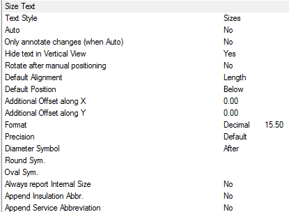
- The Style box is used to specify the AutoCAD Text Style to be used. If the Text Style Sizes is not present, then Standard is used by default.
- Text Style: Text properties are from the Style specified here. If the style does not exist, Standard is used. Height, width, font etc are defaulted from style. If only displaying in paper, the height should be the size required for plotting.
- Auto: Automatically applies the Size label to each item drawn.
- Only annotate changes (when Auto): Only applies a Size label when the items are different in size or cross section from the previous item connected from. The Auto option must be set to Yes to utilise the Only annotate changes (when Auto) option.
- Hide text in Vertical View: Hides stacked annotation in Vertical views. For example, a riser viewed in Plan would only display the base items' annotation.
- Rotate after manual positioning: An option to rotate the Size label. This is useful if the label alignments option do not allow desired alignment because of UCS or item rotation.
- Default Alignment: Sets the annotations' alignment: View, Length or Connector (default Length).
- Default Position: Sets the annotations' alignment: Below, Middle or Above (default Below).
- Additional Offset(s) X, Y: Allows additional offsets from the default position.
- Format: If the Format option is set to a value greater the 1, then the above settings are overridden as follows:
- 1: Scientific 1.55E+01
- 2: Decimal 15.50
- 3: Engineering 1'-3.50"
- 4: Architectural 1'-3 1/2"
- 5: Fractional 15 1/2"
- Precision: If set to -1, precision is controlled by the AutoCAD - Format Units setting. If set to 0-7, precision is controlled by CADmep settings (zero to seven decimal places).
- 0
- 0.1
- 0.12
- 0.123
- 0.1234
- 0.12345
- 0.123456
- 0.1234567
- 0.12345678
- Diameter Symbol: This option can be specified as follows:
- Before: Displays the Diameter Symbol before the Size label.
- After: Displays the Diameter Symbol after the Size label.
- None: No Diameter Symbol is displayed.
- Round Sym.: Enter the custom code for the desired round symbol.
- Oval Sym.: Enter the custom code for the desired oval symbol.
- Always report internal size: If to report "Airway" size or internal metal size excluding material thickness / gauge.
-
Append Service Abbreviation: This option can be specified as follows:
- Before: Service Abbreviation.
- After: Service Abbreviation.
- Append Insulation Abbr.: Insulation Abbreviation.
- Imperial: When this option is selected, uses the AutoCAD - Units (see Format settings below). When this option is not selected, the Formatting is Decimal e.g. 15.25.
Using the Sizes Command
To use the Sizes command:
- Click the Sizes icon
 .
.
- Select the items to display the sizes. This can be done using any of AutoCAD normal selection commands.
- Right-click to execute the command.
The sizes should now be displayed. The Sizes text can be moved and rotated using the AutoCAD grips or using the CADmep Move Text
 and Rotate Text
 commands.
Additional Notes
-
Selecting and reapplying any of the CADmep Label commands toggles the label on or off.
-
If the label is toggled off then on again, it will remember its original position and rotation.
-
If no annotation is displayed, check that the AutoCAD Text Style has been setup correctly.