The Slice command allows for manual oversize splitting of parts. Click on Profiler
 Slice to access the Slice command menu options and toolbar options.
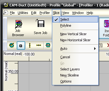

Select
 : This mode is used to select slice lines and adjust their position on the part. The lines drawn are the positions of the desired slices through the part. After the lines are in place, click to slice.
Polyline: This mode draws lines in the same manner as the Line command in Opus. Snap Modes can be used to pick points.
New Vertical Slicer
 : This command attaches a vertical line running the length of the part to the cursor, which can then be moved or snapped into position. Click to fix the line.
New Horizontal Slicer
 : This command attaches a horizontal line running the width of the part to the cursor, which can then be moved or snapped into position. Click to fix the line.
Auto
 : The ratio drop-down menu is used to specify the number of equally sized slices to cut when Auto slice is used. For example, by clicking on the drop-down menu, the value can be adjusted from 1:2 to 1:12.
Horizontal
 : Click to slice the part horizontally into the number of parts indicated by the ratio.
Vertical
 : Click to slice the part vertically into the number of parts indicated by the ratio.
Angular
 : Click to slice the part into the number of angular segments indicated by the ratio. It is useful on circular parts.
Cancel
 : Removes any slice lines that have been placed onto the part.
Go / Slice
 : Executes the slice using the lines drawn onto the development.
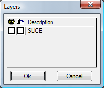
Layers: This can be used to import slice lines from draw-only layers constructed in Opus. This is useful if several parts are to be sliced in the same manner, as the slice layers can be drawn as a separate drawing. This drawing can be imported into Opus using the Cut Out
Import command, and then used to slice the part. Layers must be set up in the Profile Database before this option will function properly. Select both boxes to use the layer as a slice template.
Slice Dialog: The Slice dialog shown below includes the following options.
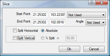
Start / End Point / Angle: Absolute points can be specified for the start / end points of the split or a start point and an angle can be given. The coordinates follow the standard X and Y annotation. The angle takes a line going to the right as zero degrees.
Split Horizontal / Vertical: This allows for a single split at either an absolute height or by a percentage of the overall height of the drawing to be made. This option is enabled by selecting either Horizontal or Vertical.
Set-up
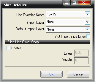
Use Oversize Seam: Select the seam from the Oversize Seams Database to be used to join the part back together.
Export Layer: Slice lines drawn will be placed on this layer.
Default Import Layer : Specifies the default layer that will be used when a Layer Slice is performed.
Auto Import Slice Lines This will automatically display lines drawn on the Default Import Layer as slice lines when Slice mode is activated.
Slice Line Offset Snap: These options specify the offset snap for the slice line.
Enable: When enabled, this automatically moves the slice line by either a specified distance or at a specified angle from the first point clicked.
Linear / Angular: Specify the desired distance or angle for the offset.