Use the Setup controls to define the simulation.
Wind Direction
Change the direction of the flow with the dial control.

Click Close to finish the command.
Wind Speed
Interactively change the wind speed with the dial control.

Click Close to finish the command.
Wind Profile
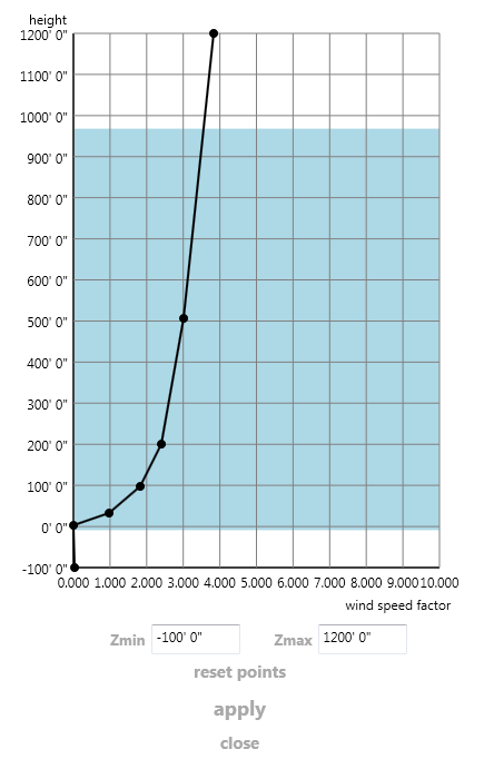
In many situations, the wind approaching a structure or building does not have a uniform velocity. The wind speed is often faster at higher elevations than at ground level. To include this effect in your simulations, click Wind Profile.
On the Wind Profile dialog, the vertical axis represents the height, and the horizontal axis is the multiplier applied to the specified Wind Speed. The colored region on the grid is the domain size of the model. The regions outside of the colored region are outside of the current wind tunnel. The default wind profile is uniform at the specified wind speed.
To specify a profile, click a point on the curve and drag to the desired location. You can drag multiple points to create the desired profile. The following is an example of a non-linear wind profile:
Resolution
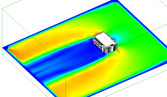
To adjust the solution fidelity, modify the grid resolution. A lower resolution grid typically runs faster, but is less accurate than a higher resolution grid. In the following example, the grid resolution is too low:
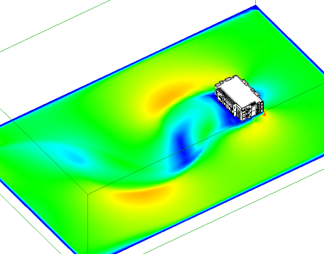
When the grid resolution is increased, the results look much better. Note that the higher resolution captures flow details that were missed by the lower resolution solution:
Domain Size
To change the size and position of the air volume around the structure, select the direction and use the sliders to grow or shrink the domain. The dimensions correspond to the labels on the faces of the ViewCube:
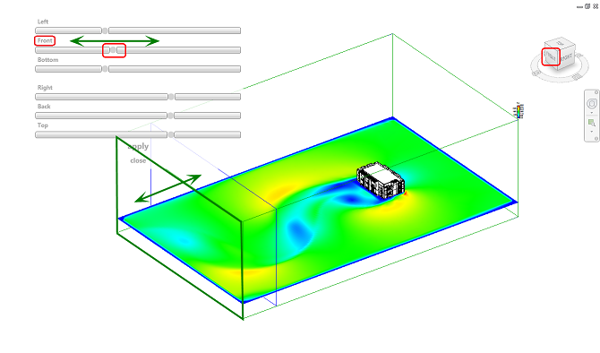
It is important to select an appropriate size for the flow domain to ensure that bounds do not artificially influence the flow.
Solution Mode
3D Simulation
To model the flow throughout the entire wind tunnel, select 3D Simulation. This mode is useful for visualizing the interactive nature of the flow around the structure. Results computed in 3D are more complete than in 2D because they encompass the entire object and the air throughout the wind tunnel. Use 3D to see where the flow is smooth and where it changes direction. Look for regions that show flow separation, recirculation, and abrupt direction changes.
2D Simulation
To model the flow on a single slice in the wind tunnel, select 2D Simulation. This mode is the fastest, and produces results on a two-dimensional slice through the model. Use it to quickly understand the wind behavior through a specific cross-section. Note that while results produced in 2D mode are conceptual, they provide a quick and valuable view of how the air moves past the design. The displayed results update as you change the wind speed and direction.
For more about the differences between 2D and 3D simulations, click here.