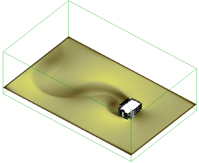
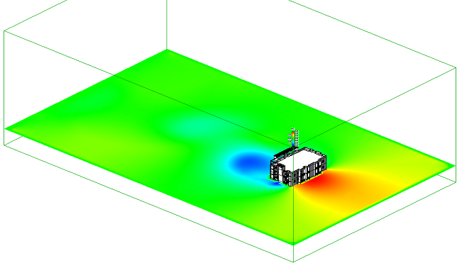
With the Results panel, you can view your results to understand how the wind moves over and around your model.
Note that for 2D simulations, changing the position or orientation of the plane causes the calculation to start over.
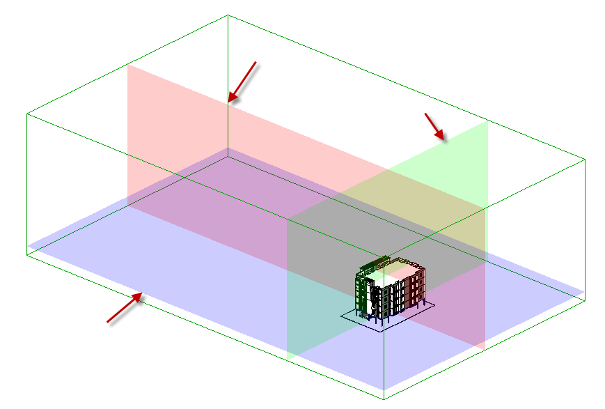
Plane Orientation
Change the orientation of the plane by selecting one of the Cartesian orientations:
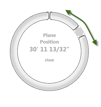
Plane Position
To move the plane, drag the dial slider to the desired elevation:
Velocity / Pressure
You can display either Velocity or Pressure.
To view wind speed, select Velocity:
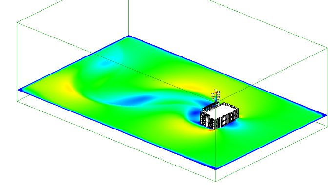
To view air pressure, select Pressure:
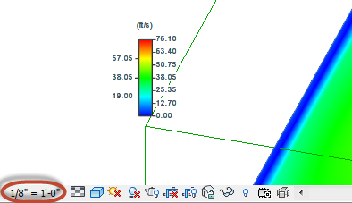
To adjust the legend size, change the model scaling from the lower left corner of the display window:
Probes
You can use Probes to extract a result value at a specific point on a Plane. To create a Probe:
- Click Add Probe.
- Click a position on the Plane.
The value at the selected position displays beside the Probe symbol:
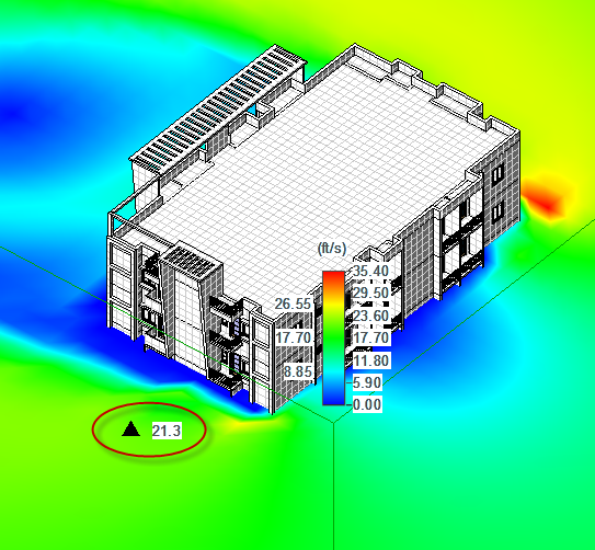
You can monitor multiple points by creating a probe at each point of interest.
To remove a probe, click Delete Probe, and select the probe.
To remove all probes, click Clear Probes.
Surface Pressure
For 3D simulations, you can view the wind-loading on the surfaces of the structure by displaying Surface Pressure:
- Click Pause (from the Flow Design panel).
- Click Display Surface Pressure from the Results panel.
To extract data at specific points on the surface, use Surface Probes:
- Click Add Surface Probe.
- Click a position on the surface of the model.
The value at the selected position displays beside the Probe symbol. You can monitor multiple locations by creating a surface probe at each point of interest.
To remove a probe, click Delete Surface Probe, and select the probe.
To remove all probes, click Clear Surface Probes.
Color Schemes
Select the visualization legend color scheme from the following options:
- Standard
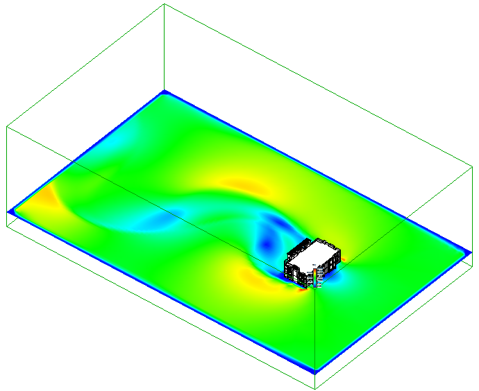
- Blue, Green Red
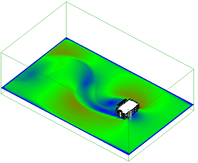
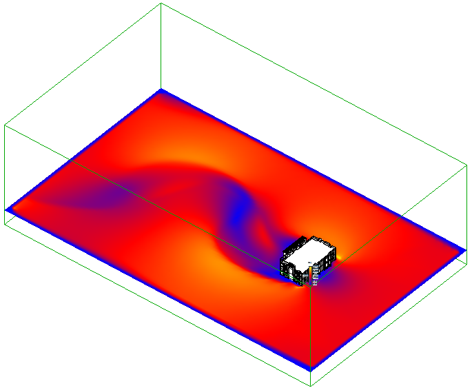
- Blue, Red, Yellow
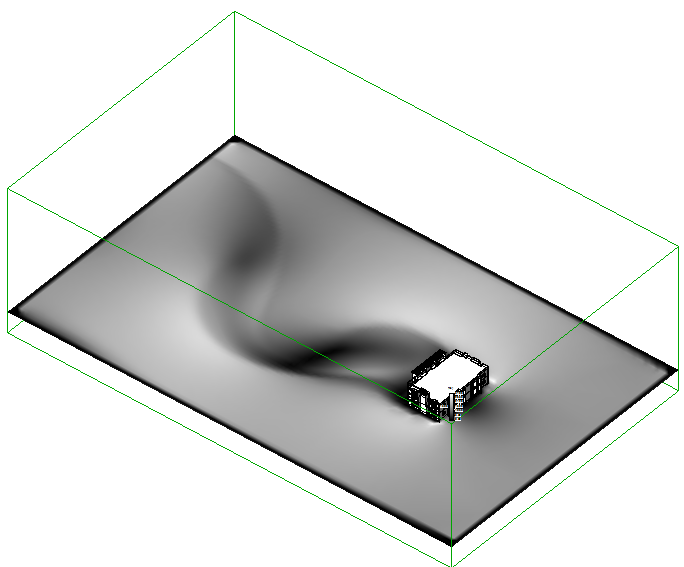
- Greyscale
- Sepia
