Joint reference
The Joint tool positions components and defines their motion relative to one another in Fusion.
Design > Assemble > Joint ![]()
The Joint dialog is split into two tabs: Position and Motion.
Position tab
Select two components and position a joint between them.
Component 1 and Component 2 sections
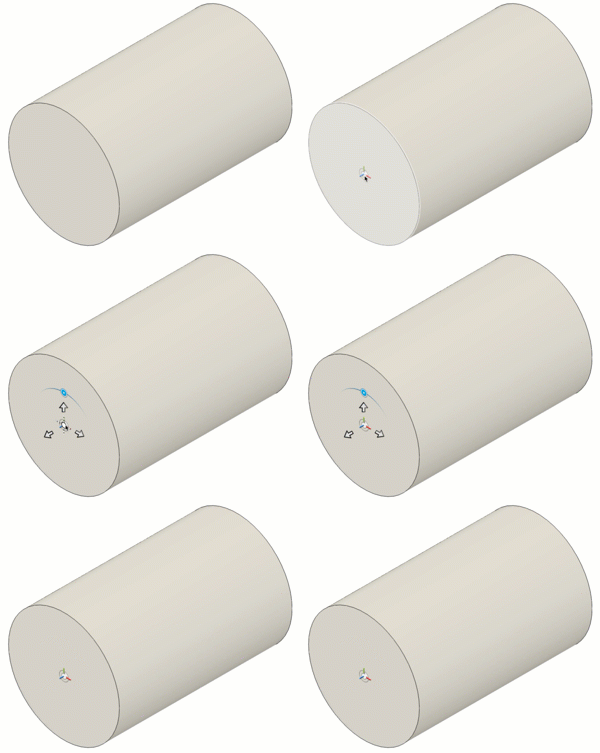
Select the joint origin mode, faces, edges, and origin snap point for Component 1 and Component 2.
One component moves to the other.
Mode
| Joint origin mode | Example |
|---|---|
 |
|
 |
|
  |
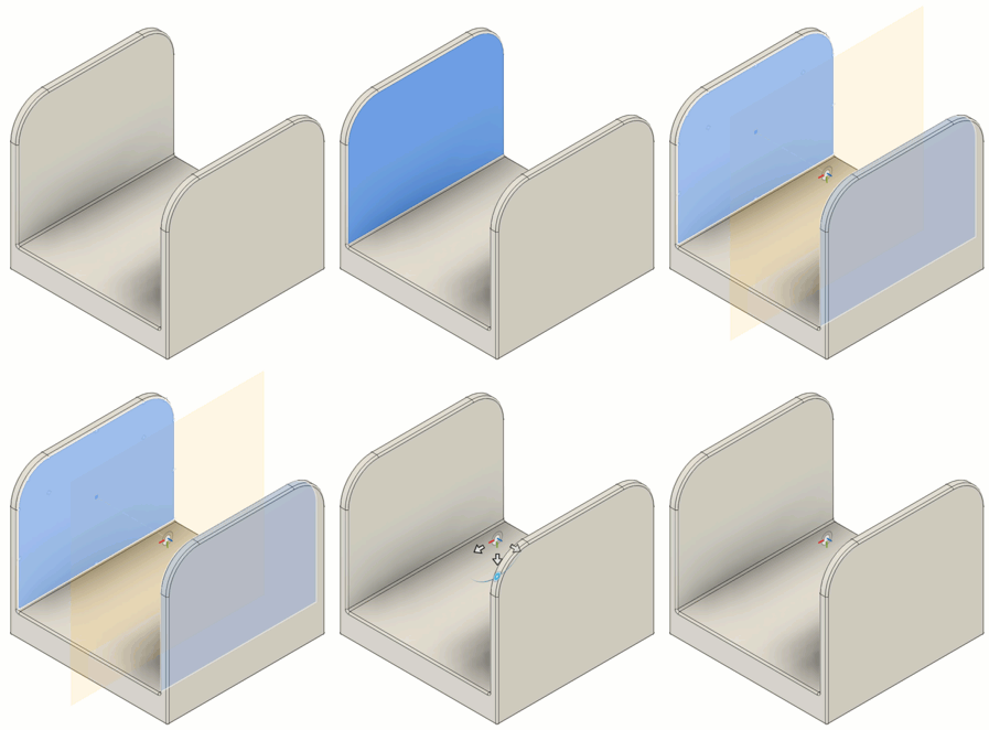
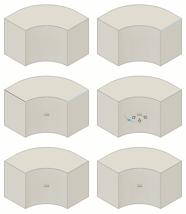
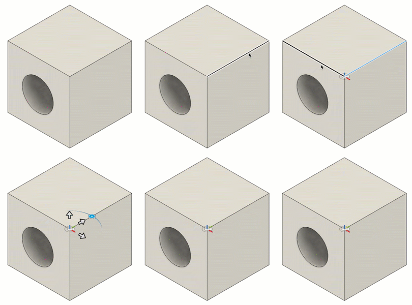
Planes, Edges, and Snap
Select the geometry to define the joint and joint origin.
| Option | Action |
|---|---|
| Plane 1 | Select a face |
| Plane 2 | Select a second face |
| Edge 1 | Select an edge |
| Edge 2 | Select a non-parallel edge |
| Snap | Select a snap point to place the joint origin |
Joint Alignment section
Adjust the angle, offsets, and orientation of the joint to align it.
Angle, Offsets, and Flip
| Option | Action |
|---|---|
| Angle | Rotate Component 1 around the joint axis |
| Offset X | Offset Component 1 along the X axis |
| Offset Y | Offset Component 1 along the Y axis |
| Offset Z | Offset Component 1 along the Z axis |
| Flips the component over the Joint Origin |
Motion tab
Specify the joint Type to define the relative motion.
Type
Select the type of joint to create, adjust rotation and translation options to control the relative motion, then animate the joint to preview the motion.
| Joint Type | Definition | Rotation/Translation |
|---|---|---|
| Locks components together and removes all degrees of freedom. | None | |
| Rotates a component around the joint origin. | Rotate | |
| Slides a component along a single axis. | Slide | |
| Rotates and slides a component on a single axis. | Axis | |
| Rotates and slides a component on two different axes. | Rotate and Slide | |
| Rotates a component around one axis normal to a plane and slides it along two axes parallel to the plane. | Normal and Slide | |
| Rotates a component around all three axes on a gimbal system (three nested rotations). | Pitch, Yaw, and Roll |
Rotation and Translation
| Option | Action |
|---|---|
| Rotate | Select axis to rotate around. |
| Slide | Select axis to move along. |
| Axis | Select axis to rotate around and move along. |
| Normal | Select axis perpendicular to plane. |
| Pitch | Select the lateral axis. |
| Yaw | Select the perpendicular axis. |
| Roll | The longitudinal axis for Roll is determined automatically once Pitch and Yaw are defined. |
Preview
Preview selected motion by animating Component 1. Click to start and stop the animation.
With All Limits
Check to preview the joint motion with all degrees of motion and limits applied.