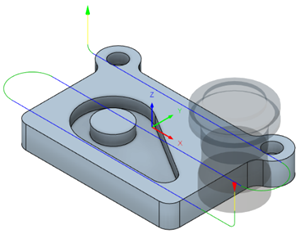
Generate a Face toolpath
On the Manufacture workspace toolbar, click Milling > 2D > Face.
The Face dialog opens.
On the Tool tab, click Select to pick a tool. If you have not created a tool to use, in the left panel of the dialog, from the Fusion Library, pick a tool from the Sample Tools library.
Tip: Face mills are best suited for the Face toolpath.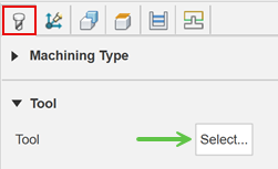
On the Geometry tab, you may contain the toolpath area using Stock Contours by selecting the edge or sketch that represents the stock to be faced. If no selection is made, the entire stock that is defined in the Setup is evaluated for machining.
On the Heights tab, adjust the vertical area to machine in Z by setting the Top Height and Bottom Height. Typically, the Top Height is set to the Stock top and the Bottom Height to the Model top.
On the Passes tab, set the Stepover to the cut spacing.
Set the Pass direction to control the angle of the cut. Zero degrees is at the 3 o'clock position, which is the X+ direction.
Optional steps:
To change the starting point of the toolpath to the opposite end of the stock block, enable From Other Side.
To ease into the first cut when cutting hard materials, enable Use Chip Thinning.
If the depth of cut is too large, use multiple steps by enabling Multiple Depths.
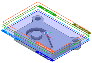
Click OK.
The toolpath is generated.