Generate a 2D Pocket toolpath
On the Manufacture workspace toolbar, click Milling > 2D > 2D Pocket.
The 2D Pocket dialog opens.
On the Tool tab, click Select to pick a tool. If you have not created a tool to use, in the left panel of the dialog, from the Fusion Library, pick a tool from the Sample Tools library.
Tip: Bull-nosed and flat end mills are best suited for removing material with a toolpath like 2D Pocket.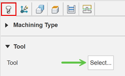
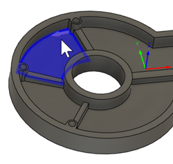
On the Geometry tab, with Pocket Selections active, select solid faces, edges, or sketches as the machining area.
Tip: Mouse over the Pocket Selections box for more information.If you've selected an edge or a sketch, verify that the red contour arrows are pointing in the correct direction. For internal pockets, the contour arrow should point counterclockwise. For bosses, the contour arrow should point clockwise. If necessary, click the contour arrow to flip its direction.
On the Passes tab, set the Maximum Stepover.
Tip: Consult your tooling supplier for stepover recommendations. Typically this value might be between 10% and 40% of the tool diameter, depending on the material type, tool size, and rigidity of the setup.Optional steps:
To machine at multiple depths, enable the Multiple Depths group and specify the Maximum Roughing Stepdown.
To avoid engaging sharp corners with the tool, increase the Minimum Cutting Radius.
To create a continuous spiral toolpath for smooth machine movement, enable Use Morphed Spiral Machining.
To reduce the NC program size, enable Smoothing.
To adjust the final Z depth, go to the Heights tab and offset the Bottom Height. The Selected contour(s) is the default final depth.
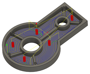
Click OK.
The toolpath is generated.