Multi-Axis Contour reference
This feature is part of an extension. Extensions are a flexible way to access additional capabilities in Fusion. Learn more.
5 Axis Machining of Surface Curves.
What We Cover In This Lesson
Multi-Axis Contour is used to machine 3D curves that lie on the face of the model. These can be actual edges from the models faces, or 3D curves that have been projected onto the face of a model. Fusion will create a toolpath that follows the selected curve/edge, while keeping normal/perpendicular to the surface of the model. Additional options will allow you to tilt the tool forwards or sideways. While you can compensate Left or Right of the selected curve, normally you would machine directly on Center of the curve.
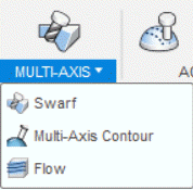
Manufacture > Milling > Multi-Axis > Multi-Axis Contour ![]()
If you would like to follow along with this video lesson, the sample part is located in the CAM Samples folder and the Ultimate sub folder.
- On the Milling tab, select Multi-Axis > Multi-Axis Contour
 .
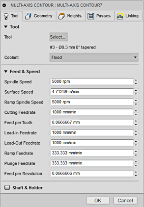
. - In the Multi-Axis Contour dialog, Tool tab, click Select to open the Tool Library.
- Change the Filter setting to select only Tapered tools.
- Select OK to close the Filter.
- Select the .3mm x 8° Tapered mill.
- Select OK to close the Library.
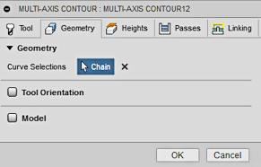
- On the Geometry tab, select the geometry as shown in the video.
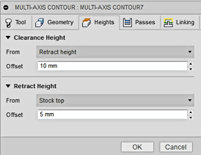
- On the Heights tab, make no changes.
- On the Passes tab, make no changes.
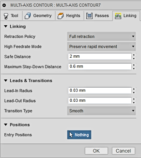
- On the Linking tab, make no changes.
- Select OK to create the toolpath.
On the Tool tab, select an appropriate tool for single point machining.
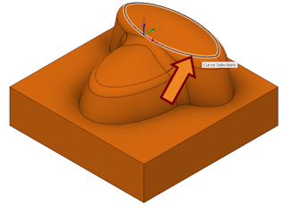
On the Geometry tab, select the chains to be machined.
 |
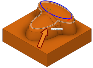 |
| Select the first chain on the dome. | The next chain will be a partial chain selection. Select the chain as shown above. |
 |
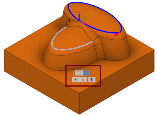 |
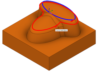
| Move your cursor off the selection and then back onto the selection. Note the color change. Click the chain again. | Select the Open Contour icon and Accept The Current Contour. |
Oh the Heights tab, keep the defaults.
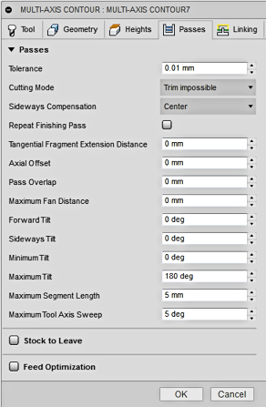 |
On the Passes tab, keep the defaults. Here are the parameters you can control: Cutting Mode handles what to do when a toolpath section has failed. Sideways Compensation places the tool on the Center of the selected curve (default). You may also select Left or Right of the curve. Tangential Fragment Extension Distance extends the Start and End of the contour. Axial Offset shifts the tool up or down through the spindle axis (Depth Control). Pass Overlap is how much to over lap the start point on a closed contour. Max. Fan Distance is a limit for large angular sweeps. Forward Tilt makes the tool lean forward (Lead) or backward (Lag) in the cut direction. Sideways Tilt makes the tool lean Left or Right from the cut direction. Min/Max Tilt prevents Fusion from tilting the tool farther than your machine is capable. Max. Segment Length is the longest segment for any single NC code move. Max. Tool Axis Sweep is the largest angular distance for any single NC code move. |
On the Linking tab, keep the defaults. The function of these parameters is the same as with most other Fusion toolpaths.