Swarf 5 Axis Toolpath reference
This feature is part of an extension. Extensions are a flexible way to access additional capabilities in Fusion. Learn more.
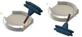
Multi-axis Side Cutting Toolpath For Milling.
What We Cover In This Lesson
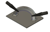
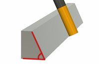
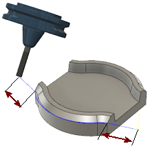
Swarf 5 Axis Milling is a side cutting process. Useful for parts with beveled edges and tapered walls. The toolpath is calculated as if there was a straight edge across the two edges that define the surface. As long as the face between those two edges is straight, you can use a Swarf cut to machine it. In this lesson, you learn how to select the geometry for creating this toolpath, along with the options to adjust and control the selection.
Manufacture > Milling > Multi-Axis > Swarf ![]()
If you would like to follow along with this video lesson, the sample part is located in the CAM Samples folder and the Ultimate sub folder.
The Tool, Heights, and Linking tabs contain all the same parameters as any other Fusion toolpaths.
Geometry tab parameters
On the Geometry tab, select the geometry to be machined for this operation. The two main parameters Drive Mode and Selection Mode have to do with:
- What type of geometry is driving the toolpath
- How to select that geometry
If you click one of the faces to be machined, Fusion will most likely find its way around the part and automatically select all relevant faces. Selecting your geometry correctly is the most important part of using the Swarf toolpath.
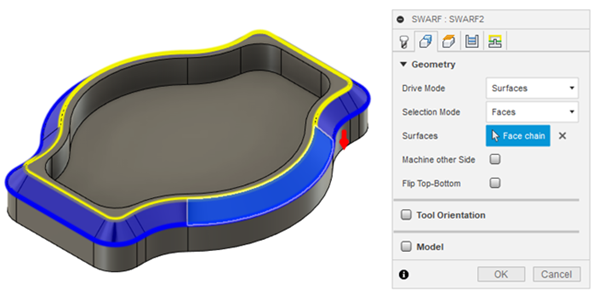
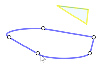
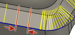
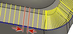
Toolpath driven by selected surfaces
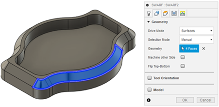
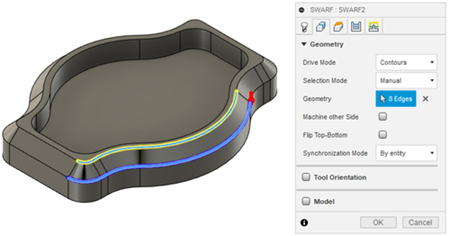
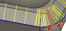
Drive Mode tells Fusion what part of the geometry determines how the toolpath is calculated. The choices are Surfaces or Contours. Surfaces follow the face of the selected surfaces. Contours follow the selected edges, or the "rails" at the top and bottom of the selected surfaces.
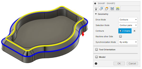
Toolpath driven by selected contour chains
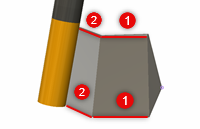
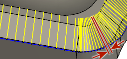
Selection Mode tells Fusion what to look for when you make your selection. The choices are Faces, Contour Pairs, or Manual selection. Faces only selects the surface geometry you pick. Contour Pairs requires you to select two sets of edge curves, an upper and a lower. Always select the lower chain first. Manual lets you select individual faces or contours for a partial Swarf toolpath.
 |
 |
Toolpath Driven by manually selected faces
Geometry shows the type and quantity of selected items. Press the "x" to deselect your geometry.
Machine other side is for tool compensation. It switches the tool position from the inside to the outside of the geometry.
Flip Top-Bottom changes the direction the tool points. This option is not available when Contour Pairs is used, because the chain selection determines the top and bottom of the cut. Always select the lower chain first.
Synchronization Mode only applies when Contour Pairs are selected.
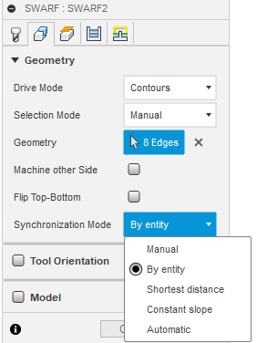
It lets you adjust how the bottom and top chain are matched together.
- Manual - Lets you select the synchronization points along the drive curves. The strategy uses these points to find tool alignments at that point along the curves. This gives you more control in scenarios with complex geometry.
- By entity - Matches the top and bottom drive curves by entities, such as edges, curves, or other geometry. This helps provide smooth tool axis movement when both drive curves have similar number of entities.
- Shortest distance - Aligns the tool to follow the shortest distance between the top and bottom drive curves.
- Constant slope - Maintains a constant angle between the drive curves. Useful for creating a consistent toolpath when machining slopes or angled surfaces, helping provide a uniform cut along the toolpath.
- Automatic - Automatically determines whether to use By Entity, Shortest Distance, Constant Slope, or a slightly different synchronization method depending on the geometry. In most cases, this option may provide the desired result.
 Manual |
 By entity |
 Shortest distance |
 Constant slope |
 Automatic |
Passes tab parameters
The Passes tab contains controls that modify the toolpath.
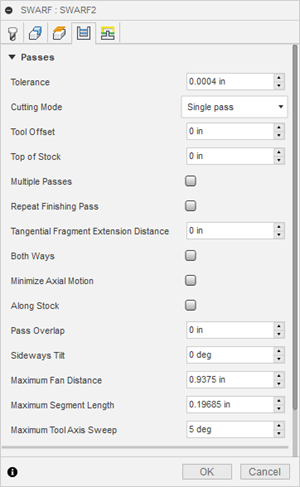
Tolerance is the accuracy to use when calculating the toolpath. Cutting Mode lets you take multiple cuts. Those cuts can be from the top down, or the bottom up. Spiral and Morph will try harder to keep the tool down on the part. Trim options allow you to rapid past any open areas. This reduces your cycle time. Selecting a Cutting Mode other than Single Pass will open up a new set of parameter on the lower section of the dialog.
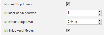
Checking Manual Stepdowns allows you to specify a Number of Stepdowns along with a Maximum Stepdown amount. Minimize Axial Motion reduces any "noise" or excessive motion in the spindle axis.
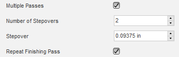
Checking the box for Multiple Passes, opens a new set of parameters to allow multiple side cutting of the profile. Specify the Number of Stepovers and Stepover amount to add extra outer passes. Repeat Finishing Passes adds a "spring cut" pass with no additional stock.
Top of Stock allows you to define extra stock over the part. Both Ways forces the toolpath to cut in both directions, giving you climb and conventional cuts.
Tangential Fragment Extension Distance extends the start cut and end cut tangentially by the value you specify.
Tangential Fragment Extension Distance
Maximum Fan Distance specifies the maximum distance over which to fan the tool axis.
Sideways Tilt tilts the tool away from the face by the amount you specify.
Maximum Segment Length specifies the maximum length of a single segment for the generated toolpath. A larger distance can reduce the file size, but make the cut coarse. The calculated toolpath will always be within the specified Tolerance.
 |
 |
| Maximum Segment Length 0.150 in | Maximum Segment Length 0.050 in |
Maximum Tool Axis Sweep Specifies the maximum angular change in a single tool axis sweep, for the generated toolpath. A larger distance can reduce the file size, but can also make the cut coarse. The calculated toolpath will always be within the specified Tolerance.
 |
 |
| Angular sweep of 10 degrees | Angular sweep of 5 degrees |