4th Axis Wrap Toolpath reference
Rotary Contouring Toolpath Creation.
What We Cover In This Lesson
Wrap Toolpath can analyze the chain you select and create a 4th axis rotary contouring toolpath. This option is only available in the 2D Adaptive, 2D Pocket and 2D Contour Toolpaths. While you have the capability of using a 2D sketch or a 3D model for your geometry, we recommend always selecting your geometry from a 3D model, so your toolpaths maintain associativity. The concept is fairly simple, you select your edges to be machined and select the face that represents the radius of the cylindrical part. Fusion will calculate an un-wrapped geometry, create a toolpath, then re-wrap the toolpath around the specified radius.
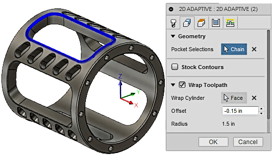
Wrap Toolpath functionality can be found on the Geometry Tab in the 2D Adaptive, 2D Pocket and 2D Contour Toolpaths. It's recommended that you select this option before you try to select your geometry. Fusion will change your geometry selection capabilities if it knows you're planning to create a 4th axis wrapped toolpath.
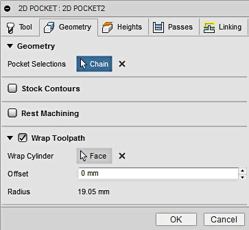 |
Wrap Cylinder allows you to select the outer face of a cylindrical part, so Fusion can determine the Radius for the wrapped toolpath. This selection must be a cylinder, NOT a cone or irregular surface. Offset can be used to offset in or out of the selected chain. |
If you would like to follow along with this video lesson, the sample part is located in the CAM Samples folder and the Ultimate sub folder. REMEMBER: if you see a Red ring, it's signifies a Left mouse click. A Blue ring signifies a Right mouse click.
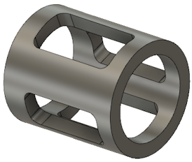
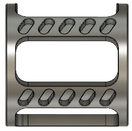
Much of your success will depend on the model you use. Rotary machining a pocket into a cylinder will generate a tapered wall because of the angle of the tool pointing in towards the center of the part. Both parts below appear to be similar, but the way the pocket is designed will determine if you need a simple 2D Pocket cut straight down into a cylinder (indexing motion), or a 4th axis rotary contour motion.
 |
 |
|
 |
 |
|
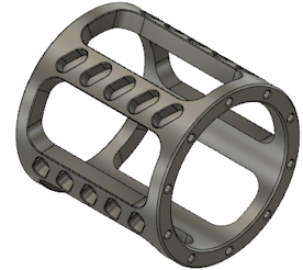
| You can see the walls of this part go straight down. Simply create a 2D toolpath straight thru that plane. This is not a 4th axis rotary pocket. | In this part you can see the walls across the Y axis are tapered, but the walls across the X axis are straight. This is a 4th axis rotary pocket. |
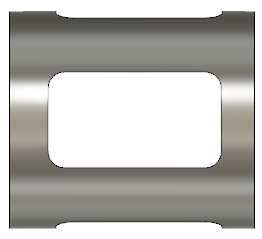
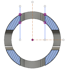
If the walls across the X axis need to be tilted/tapered, you might need a 5 axis milling machine. On this end view of the cylinder (below) you can see the taper of the walls better.
 |
 |
|
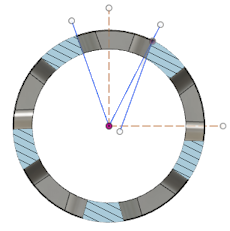
| From the end view, you can see the walls of the pocket are not pointed towards the center of the part. It's a straight plunge thru the top plane. | Here you can see how the left pocket wall tapers thru the center line of the cylinder and how the right wall is close, but not exact. In this case, the best you can do is use the Offset parameter to move the chain selection up or down, to get closer to the actual angle. The direction for the offset will depending on whether you selected the lower or upper edge of the pocket. |
It is important to set your axis orientation so they are pointing in a direction that makes sense for your machine and rotary combination. In the picture shown above, the X axis points thru the center of the cylinder. This would most likely be an "A" axis on a Vertical Machining Center. Setting the correct plane and orientation will effect your Postprocessor and NC output.
Ready For The Next Level: Watch This Intermediate Wrapped Toolpath Training.