Generate a Steep and Shallow toolpath
This feature is part of an extension. Extensions are a flexible way to access additional capabilities in Fusion. Learn more.
On the Manufacture workspace toolbar, click Milling > 3D > Steep and Shallow
 .
.The Steep and Shallow dialog opens.
On the Tool tab, click Select to pick a tool. If you have not created a tool to use, In the left panel of the dialog, from the Fusion Library, pick a tool from the Sample Tools library.
Tip: Bull-nosed and ball type end mills are best suited for the Steep and Shallow finishing toolpaths.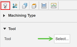
On the Geometry tab, you may contain the toolpath area with a Machining Boundary and then select the face, edge, or sketch that represents the area to be machined. If no selection is made, the entire model will be evaluated for machining within the defined Stock box.
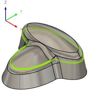
To engage the toolpath to the full extents of the boundary or surface edge, enable the Contact Point Boundary parameter.
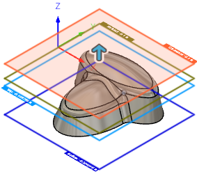
On the Heights tab, adjust the vertical area to machine in Z, by setting the Top Height and Bottom Height of the cutting area.
On the Passes tab, set the Stepdown of the cut spacing for the Steep cuts. A smaller distance will create a smoother surface finish.
Set the Stepover of the cut spacing for the Shallow cuts. A smaller distance will create a smoother surface finish.
Optional steps:
To control the Stepover and Stepdown value automatically based on the desired surface finish, enter a Cusp Height value.
To control the intersection of these 2 cutting styles, use the Threshold Angle and the Overlap Distance parameters.
To control the order of the cuts, change the Priority parameter.
To control the style of the Shallow cut, change the Type parameter.
To reduce the NC program size, enable Smoothing.
To avoid machining flat areas, on the Geometry tab, enable Avoid Flat Areas.
Click OK.
The toolpath is generated.
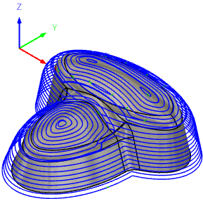
Shown with the Contact Point Boundary and the Shallow Continous parameters enabled.