Setting Machining Heights reference
Control the machining area by depth for most machining strategies.
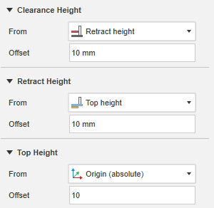
You can control the machining area by depth for most machining strategies on the Heights tab. The machining area is defined by the Top Height and Bottom Height. On the Heights tab, you can also control the retracts by setting the Clearance Height, Retract Height, and Feed Height. Generally, each height is offset from the other but you can also set them to be absolute. The absolute heights are always in relation to the operation origin which defaults to the WCS defined in the setup.

The Heights tab
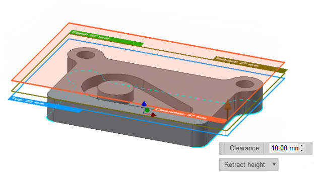
You can preview the height planes in the canvas when the Heights tab is active. The plane dimensions are derived from the bounding box of the geometry.

The Clearance Height is orange, the Retract Height is olive green, the Feed Height is green, the Top Height is light blue, and the Bottom Height is dark blue.
Each of these modes puts the associated height in a relative mode where the height is in relation to the selected height. As an example, if you select Retract height in the Clearance Height drop-down list and the clearance height offset is 5 mm, the actual clearance height will be 5 mm above the retract height. All height modes are fully associative such that the heights update automatically when the model and stock changes.
Adjust heights from the canvas
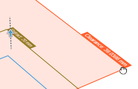
As an alternative to setting heights on the Heights tab, you can adjust heights directly from the canvas by clicking and dragging the height planes.
