Cutter Radius Compensation reference
Cutter Radius Compensation, also know as Cutter Compensation, allows you to move the toolpath to the outside, the inside or directly on the selected profile. You can select the type of compensation performed from the Compensation Type drop-down menu on the Passes tab of the 2D Contour dialog.
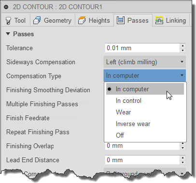
Changing the *Compensation Type***
When Fusion shows a preview of a toolpath, it is always the calculated (e.g. uncompensated) toolpath that is shown. The simulation and verification modes show the compensated toolpath as it would be run by the CNC machine.
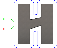
In computer
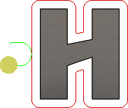
Tool compensation is calculated automatically by CAM, based on the selected tool diameter. The post processed output contains the compensated path directly, instead of G41/G42 codes.
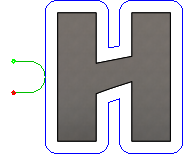
Preview
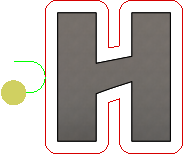
Simulation
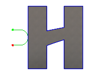
In control
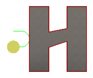
Tool compensation is not calculated, but rather G41/G42 codes are output to allow the operator to set the compensation amount and wear on the machine tool control.
Preview

Simulation
Wear
Similar to the In Computer option, but also outputs the G41/G42 codes. This lets the machine tool operator adjust for tool wear at the machine tool control by entering the difference in tool size as a negative number.
Preview
Simulation
Inverse wear
Identical to the Wear option, except that the wear adjustment is entered as a positive number.
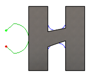
Off
No radius compensation is performed and the tool center simply follows the selected geometry.
Preview
Simulation