Shaft and Holder Modes reference
Explore the different shaft and holder modes.
The 3D strategies in Fusion fully support user-defined shafts and holders. When using a tool with a holder, you can choose between one of five different shaft and holder modes, depending on the machining strategy. Collision handling can be done for both the tool shaft and holder, and they can be given separate clearances.
- Disabled - Ignores any shaft/holder collisions.
- Pull away - The toolpath pulls away from the workpiece to maintain a safe distance between the shaft and/or holder.
- Trimmed - Sections of the toolpath that result in safe distances between the shaft and/or holder being violated are trimmed away.
- Detect tool length - The tool is automatically extended further out of the holder to maintain the specified safe distance between the shaft and/or holder and the workpiece. A message indicating how far the tool is extended out of the holder is logged.
- Fail on collision - The toolpath calculation is aborted and an error message logged when the safe distance is violated.
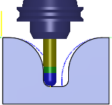
The various options produce different toolpaths that can be seen in the following images:
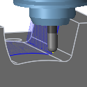
Disabled
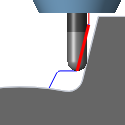
Pull away
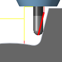
Trimmed
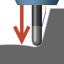
Detect tool length
Detect tool length
With this option selected, Fusion automatically calculates the minimum tool length required to keep the holder free of the part with a given Holder Clearance. When the toolpath is calculated, the "Body length" of the tool definition is updated to the minimum length required.
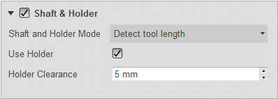
Setting Detect tool length with a holder clearance distance of 5 mm
The following warning is output to the log when generating the toolpath with Detect tool length active and the tool is too short: Warning: The tool length has been updated from 25 mm to 35.9453 mm to ensure that the holder doesn't collide with the part.
At the same time, the tool is updated.
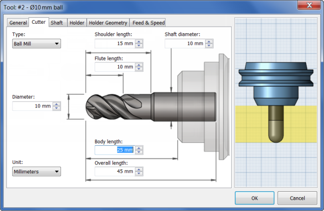
The original tool
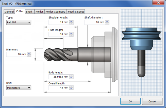
The updated tool
The following example shows the difference on the model with a simple toolpath:
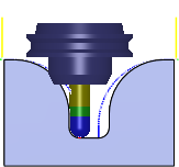
Before tool length detection
After tool length detection with a holder clearance of 5 mm