2D Chamfering reference
2D Chamfering lets you mill a beveled edge on the part. There are two ways to program a chamfer, depending on whether the CAD model already has chamfered features or not. In both cases, you can use the 2D Contour strategy to chamfer the model.
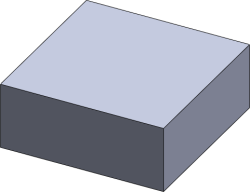
CAD model with no chamfer
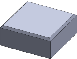
CAD model with chamfer feature
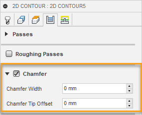
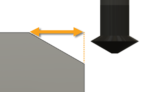
Chamfer Width
The (additional) width of the chamfer. The width of the chamfer is defined by the width of the cut, for example:
For edges that are not chamfered, this is the final width of the chamfer.
For edges that are chamfered, this is an additional offset which removes extra material from the part.
Chamfer Tip Offset
This is added to the toolpath depth, while keeping the tool in contact with the selected edge by adjusting the toolpath radial offset.
Both chamfered and unchamfered CAD models can be handled with the Chamfer Width and Chamfer Tip Offset parameters.
In the case where the model edges are not chamfered, set the width to the desired amount, and then adjust the tip offset depending on the size of the tool.
If the model has already been chamfered, the easiest way is to select the lower edge of the chamfer. This puts the tool chamfer corner at this position, and you only need to adjust the tip offset if you want to go some distance below the lower edge.