Generate a Flat toolpath
On the Manufacture workspace toolbar, click Milling > 3D > Flat.
The Flat dialog opens.
On the Tool tab, click Select to pick a tool. In the left panel of the dialog, from the Fusion Library, pick a tool from the Sample Tools library.
Tip: Flat bottom and bull-nosed end mills are best suited for the Flat finishing toolpaths.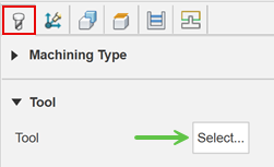
On the Geometry tab, you may contain the toolpath area with a Machining Boundary and then select the edge, or sketch that represents the area to be machined. If no selection is made, the entire model will be evaluated for machining within the defined Stock box.
(Optional) To detect how much material has been removed from previous operations and to only machine the remaining material, select the Rest Machining checkbox.
(Optional) To generate a toolpath over holes, click the Machine Over and Into Holes/Pockets checkbox.
If you are machining over holes, enter a Max Hole Size limit to control which holes to generate a toolpath over.
On the Passes tab, from the Type drop-down menu, select the type of toolpath to generate over flat areas of the model.
Tip: Place the pointer over the Type drop-down menu for more information on which type to select.If you selected Pocket from the Type drop-down menu:
To generate a spiral-style toolpath for better surface finish, click the Spiral checkbox.
To reduce sharp corners in the toolpath, increase the Smoothing Deviation slider.
If you selected Parallel from the Type drop-down menu:
To manually specify the direction of the passes, from the Pass Direction drop-down menu, select Manual.
With Manual selected, enter a Manual Pass Direction.
Set the Stepover to adjust the cut spacing. A smaller distance will create a smoother surface finish.
Click OK.
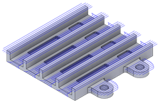
The toolpath is generated.