Example: Add work-holding equipment and patch a surface
The following example shows how to add work-holding equipment to a manufacturing model and then how to add a patch to a surface to generate the desired toolpath.
To follow the example, create a project and save the following sample files to a folder of your choice:
- 2D strategies: Data Panel > Samples area > CAM Samples > 2D Strategies (do not select 2D Strategies - Complete).
- Generic Vise: Data Panel > Samples area > CAM Samples > Workholding > Generic Vise.
Add work-holding equipment to a part
Open the 2D Strategies file and enter the Manufacture workspace.
On the toolbar, from the Setup drop-down menu, click Create Manufacturing Model to create a manufacturing model. The Manufacturing Models node appears in the Browser containing a manufacturing model.
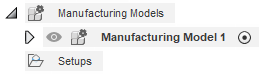
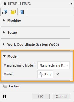
In the Browser, right-click the manufacturing model (Manufacturing Model 1) and select Create Setup from Manufacturing Model. The Setup dialog is displayed and the manufacturing model is automatically specified as the model geometry considered for toolpath calculation.
Click OK to create the Setup.
In the Browser, double-click Manufacturing Model 1 to edit the manufacturing model. Editing the manufacturing model takes you to a contextual environment where you have access to common design tools.
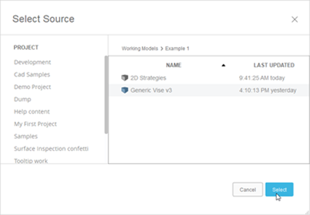
In the contextual environment toolbar, select Insert > Insert Derive to begin adding the vise to the manufacturing model. The Select Source dialog appears.
Note: You cannot currently insert the work-holding directly into a manufacturing model through the data panel. Instead, use the Insert Derive workflow.Navigate to the location where the Generic Vise is saved and click it to specify the file you want to look into for derive.
Click Select. The file containing the vise is opened and you can select the bodies or components that you want to derive.
In the Browser, select the three components: Base:1, Rear Jaw:1, and Front Jaw:1. Three components appear in the Derive dialog.
Note: Selecting objects from the canvas imports them as bodies. Selecting them from the Browser imports them as components.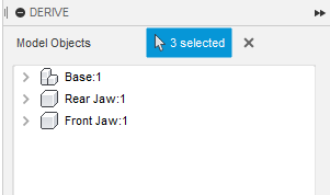
Click OK. The vise gets added to the manufacturing model. Now, the part and the vise are both considered as one manufacturing model.
 Note: The vise may cover the part on the canvas initially. In the next steps, you locate the part into the vise.
Orient the vise and specifying a fixture in the Setup
For manufacturing, the vise helps provide a visual representation when programming operations and more importantly also lets Fusion know what to avoid when generating toolpaths.
While still in the contextual environment, on the toolbar, select Modify > Move/Copy to begin orienting the vise.
In the Move/Copy dialog, from the Move Object list, select Components.
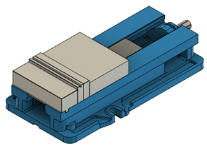
In the Browser, select the Base:1, Rear Jaw:1, and Front Jaw:1 and position the vise so the part sits near the smaller jaw of the vise then click OK.
On the toolbar, select Modify > Move/Copy and move the Front Jaw:1 so it clamps onto the part (visually) then click OK.
 Note: You can use joints to accurately clamp a part. For the purposes of this example, it is fine to visually approximate that the part is clamped.
On the toolbar, click Finish Edit to exit the contextual environment.
In the Browser, right-click Setup1 and select Edit. Although the vise and the part are now one manufacturing model, you need to let the Setup know that the vise is a fixture.
On the Setup dialog, activate the Fixture group and select Base:1, Rear Jaw:1, and Front Jaw:1 from the Browser.
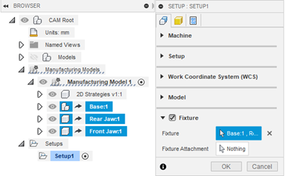
On the Setup dialog, click OK. The vise is now added to the Setup as a fixture so any toolpaths within the Setup avoid the fixture.
Patch surfaces for toolpath generation
On the Manufacture workspace toolbar, click Milling > 3D > Parallel to generate a parallel toolpath.
Select the 13 - 6mm L30mm (bull nose end mill) tool, which can be found in the Fusion Library > Tutorial - Metric area in the tool library.
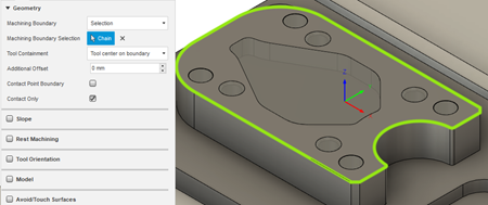
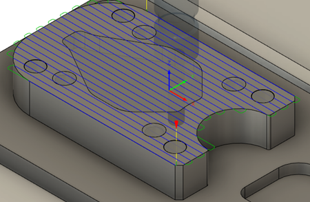
From the Geometry tab, in the Machining boundary drop-down list, choose Selection then select the upper edge of the part as the machining boundary. This limits the toolpath calculation to the area within this boundary.
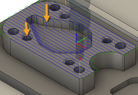
Click OK to generate the toolpath. As a result of the pocket and holes on the model, the toolpath dips into the model. Since the areas it dips into have not been machined yet, there is a risk of breaking the tool or damaging the part. To generate the desired toolpath, you have to patch up these surfaces.
In the Browser, under the Manufacturing Models node, double-click Manufacturing Model 1 to enter the contextual environment.
In the Browser, hover the mouse on 2D Strategies v1:1 so the Activate component button appears then click it to activate that component.
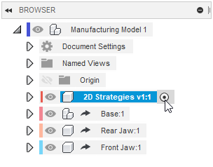 Note: Activating the component means any changes made to the part are added to the Browser structure underneath 2D Strategies v1:1 instead of the main level (Manufacturing Model 1). This is helpful for assemblies that contain multiple components because the relevant changes are contained with the component's Browser structure so they are easy to find.
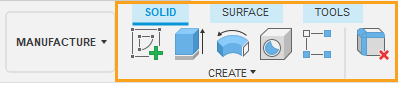
On the toolbar, click Surface tab > Create panel > Patch command then patch the holes and pocket in top area of the part as shown. If a dialog appears telling you some components have moved, click Capture Position.
On the toolbar, click Finish Edit to exit the contextual environment. On returning back to the manufacture environment, notice that the parallel toolpath in Setup1 is not invalidated. This is because you need to let the parallel strategy know that you've added surfaces to consider.
In the Browser, right-click the parallel toolpath and select Edit.
From the Geometry tab, activate the Model group and select the patches you previously added. There should be 9 faces selected all together as the Model Surfaces.
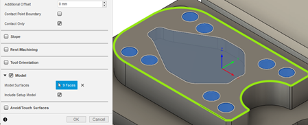
Click OK to regenerate the toolpath. As a result, the toolpath no longer dips into the holes and pocket, giving you the desired toolpath.
In summary, this example showed you how to use the manufacturing model to add work-holding equipment (a vise) to a part and then how to add patches to surfaces to get the desired toolpath. The patches were added to the manufacturing model but not selected as part of the Setup like how the vise was. As a result, the vise gets considered for each toolpath you generate. In contrast, the surfaces only get considered when you select them as model surfaces for each toolpath.
If you want any geometry to automatically be considered for each toolpath generation, then you can add it to the Model group in the Setup dialog.
The changes made to this manufacturing model (adding the vise and patching the surfaces) optimize the programming of operations in the manufacture workspace while leaving the design data unaffected. If you now switch to the Design workspace, you see the original production part.