Generate a Rotary Contour toolpath
This feature is part of an extension. Extensions are a flexible way to access additional capabilities in Fusion. Learn more.
On the Manufacture workspace toolbar, click Milling > Multi-Axis > Rotary Contour
 .
.The Rotary Contour dialog opens.
On the Tool tab, click Select to pick a tool. If you have not created a tool to use, In the left panel of the dialog, from the Fusion Library, pick a tool from the Sample Tools library.
Tip: Bull-nose end mills are best suited for the Rotary Contour toolpath.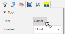
On the Geometry tab, you may contain the toolpath area with a Machining Boundary and then select the edges, or a sketch that represents the area to be machined. If no selection is made, the entire model will be evaluated for machining within the defined Stock box.
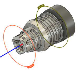
Set the orientation of the rotary axis. On the Rotary Axis group, select an option from the Rotary Axis drop-down menu. For example, select Setup X Axis if you have set the X axis of your Setup to match the rotary axis in your machine tool.
Tip: Mouse over a parameter for more information.Set the rotary axis location by selecting an option from the Origin drop-down menu. For example, select Setup WCS Origin if you have set the origin of your WCS in your Setup to match the center of the rotary axis in your machine tool.
From the Front Mode drop-down list, select a front boundary to specify where the toolpath should start. If you want to select a face on your model from the canvas, choose Selection then click a face on the model on the canvas.
From the Back Mode drop-down list, specify where the toolpath should end.
In the Radii tab, on the Outer Radius group, from the From list, select an option to specify the outer radial limit of the toolpath.
On the Inner Radius group, from the From list, select an option to specify the inner radial starting location of the toolpath.
In the Passes tab, on the Stepdowns group, enter a Maximum Stepdown value.
Optional steps:
- To machine conical surfaces effectively, in the Geometry tab, select the Fixed Tilt for Cone Machining checkbox and enter a Cone Angle.
- To remove material effectively when performing a stepdown, in the Passes tab, select the Automatic Stepdown checkbox then enter a Minimum Stepdown distance.
- To avoid cutting small areas, such as pockets that are of similar width to the tool diameter, select the Exclude Small Areas checkbox and then enter a threshold percentage.
- To machine over small gaps in the stock instead of performing linking moves for quicker machining, select the Machine Over Gaps checkbox and then enter a Max Gap Size distance.
Click OK.
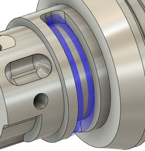
The toolpath is generated.