Workflow: Additive (FFF)
Set the document's units
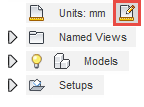
In the Browser, place the pointer over Units.
The Change Active Units button appears.
Click Change Active Units.

From the drop-down menu, select Inch or Millimeter.
Click OK.
Create an additive setup
On the Manufacture workspace toolbar, click Additive > Setup > New Setup
 .
.The Setup dialog opens.
In the Machine area of the Setup dialog, click Select to choose a machine.
The Machine Library dialog opens.
In the left panel of the dialog, select the Fusion Library and search for the Autodesk Generic FFF machine.
Note: If you cannot find the machine, in the right panel of the dialog, ensure you are filtering for Additive capabilities and FFF technologies.Choose the Autodesk Generic FFF Machine and click Select.
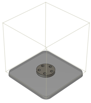
A preview of the machine appears on the canvas.
In the Machine area of the Setup dialog, next to Print Settings, click Select to choose print settings.
The Print Settings Library opens.
On the left panel of the dialog, select Fusion Library.
From the print settings, choose ABS 1.75mm and click Select.
In the Arrangement area of the dialog, ensure the Arrangement checkbox is selected.
On the Setup dialog, click OK.
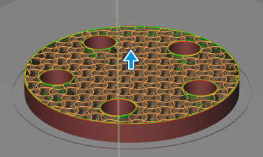
Clicking OK generates an additive toolpath.

Simulate the additive toolpath
In the Browser, if necessary, expand the Setup node.
Right-click the Additive Toolpath node and click Generate.

From the Additive toolbar, choose Actions > Simulate Additive Toolpath.
The Simulate dialog opens and simulation player controls appear at the bottom of the canvas.

Press the play button to begin simulation.
When simulation is complete, keep the Simulate dialog open to generate the machine code.

Generate the machine code
With the Simulate dialog open, click Post Process.
The NC Program dialog opens.
Click Post.
Note: If you get a prompt to overwrite a file, go back and change the File Name to avoid overwriting. Alternatively, click Yes to overwrite.In the prompt that appears on the bottom-right of the canvas, click View NC Code.
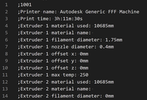
Tip: If the prompt disappears, you can also right-click the NC Program in the Browser and click Open NC Output Folder.The NC Code opens for you to view. The NC Code is the file that contains the instructions for the machine to manufacture the part.
 Note: You may need to choose to open the NC Code in a text editor that is installed in your computer.