Component Sources reference (nesting)
This feature is part of an extension. Extensions are a flexible way to access additional capabilities in Fusion. Learn more.
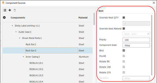
This reference topic describes the controls on the right side of the Component Sources dialog that are used for setting global nesting defaults for these components. These defaults can be overridden in Process Material Library and Nest Study settings.
Click Manufacture > Fabrication > Milling > Sources > Component Sources.
QTY: Sets the number of instances of the selected component to include in the nest.
Override Nest QTY: Overrides the quantity of the components that came from nest preparation.
Override Nest Material: Assigns a different material to the component instead of the default one. The materials that appear in this list are from the Process Material library.
Material: Sets the material for the component from the Process Material library.
Priority: Sets the order in which nesting places parts on the sheet. Fusion applies priority before part size. Lower values are nested first, even when that placement is less optimal. Values must be between 0 and 100.
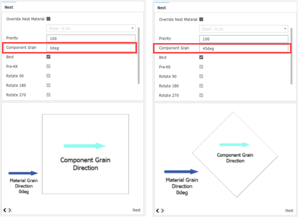
Component Grain: Specifies the grain direction on the component. The preview reflects how the component aligns to the sheet grain. For materials such as wood, this affects how the component is oriented on the sheet.
You can also preview the orientation of the component on the sheet. The image below shows the difference between using a Component Grain of 0 degrees (left) and using a Component Grain of 45 degrees (right).
Bind: Controls whether shapes follow material-defined nesting properties. Deselect Bind to allow those properties to be overridden and to enable the controls that follow Bind in the dialog.
Pre-Kit: Allows two instances of a part to be nested together at opposing angles to save space. The pair is treated as a single part in the nest. A kit is not created if no space is saved.
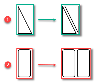
- Two instances are smaller than twice one, so space is saved.
- Two instances are not smaller than twice one, so no space is saved. No kitting takes place.
Rotate 90, Rotate 180, Rotate 270: When selected, allows the component to be rotated by that angle while nesting.
- Preview: Scroll through different views of the part
 .
. Deviation: Specifies the allowable deviation from the defined orientation. For example, a value of 10 allows a 90-degree orientation to vary between 80 and 100 degrees. Values must be between 0 and 360.
Increment: Specifies the step size used within the allowed orientation deviation. For example, with a deviation of 10 and an increment of 2, orientations can vary by 2, 4, 6, 8, and 10 degrees. Values must be between 0 and the current Deviation value.