Nest Preparation reference
This feature is part of an extension. Extensions are a flexible way to access additional capabilities in Fusion. Learn more.
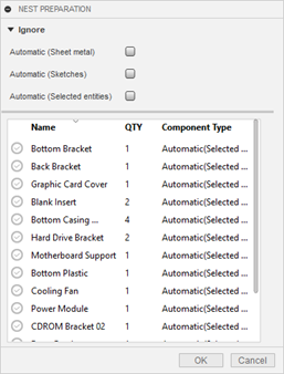
This reference topic describes the Nest Preparation dialog. Available controls can change depending on what is selected in the dialog.
Click Design > Tools > Nest > Nest Preparation.
Ignore
Under Ignore, set which types of objects should not be included in your nest.
- Automatic (Sheet metal): excludes all sheet metal parts
- Automatic (Sketches): excludes all sketches
- Automatic (Selected entities): excludes non-sheet metal solids
Component Type drop-down menu
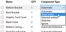
In the Component Type column, click items to open a drop-down menu that you use to set how you want Fusion to treat individual objects for nesting. The settings you make for each part override the Ignore settings at the top of the dialog.
The benefits of assigning component types include:
- Saves processing time when Fusion does not have to analyze the object to determine what type it is
- Gives you flexibility to control which face of an object is used for nesting
- Gives you flexibility to set extrusion direction and thickness for some parts
The remaining sections in this topic describe the available options in the drop-down menu. The controls at the bottom of the dialog vary depending on what option you select.
Automatic
Fusion determines what kind of object this is and how best to treat it as a nestable item; for example, if the object is sheet metal, Fusion detects this and looks for a flat pattern to nest. The detected type is shown in parentheses; for example, "Automatic (Sheet metal)." Fusion checks for types in the order they appear in the drop-down menu; that is, sheet metal, selected entities, and finally sketches. In other words, if this is a sheet metal part without a flat pattern, Fusion will treat it as a selected entity.
Sheet metal
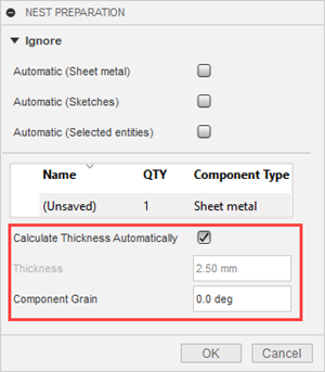
Fusion checks for a flat pattern to use for nesting. Additional controls that appear in the dialog when using a sheet metal component type:
Selected entities
Fusion will nest the parts you select using the controls that are provided in the lower part of the dialog. This can be useful if you only want to nest certain parts of an object, or want to change which face is used for nesting. (By default, Fusion uses the largest face for nesting.) You will also be able to manually set allowable rotation values for the part in the Component Sources dialog.
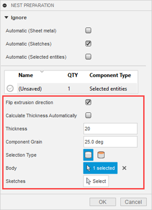
Additional controls when Selected entities is selected:
Sketches
Fusion determines the largest face of the sketch and uses it for nesting.
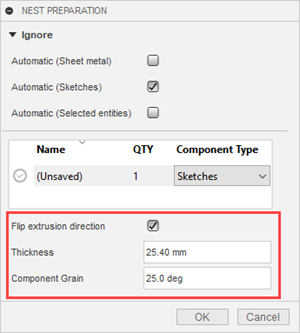
Additional controls when Sketches is selected:
Ignore (drop-down menu item)
The part is not nested.
Reference
Definitions for all the additional controls that appear depending on the Component Type:
Flip extrusion direction: Like with Selected entities, flips the direction in which you want the item placed on packaging.
Calculate Thickness Automatically: Fusion determines the thickness automatically from the selection. In cases where the packaging you have is not sufficient, you can manually enter a Thickness value.
Thickness: Specifies the detected thickness of the object, but you can change this if you want. If you do, use a value that corresponds to packaging that will be used in your nest, since Fusion will try to nest the object on appropriate packaging.
Component Grain: Specifies the direction of the grain on the component for materials such as wood. This affects how the component is oriented on the sheet. The orientation is such that the grain on the component aligns with the grain on the sheet. The grain of the sheet is specified in the Process Material Library.
Selection type: switches the selection type between Body
 or Planar Face
  . This gives you the option of using a different face for nesting, instead of letting Fusion use the largest face on the object.
Body or Planar face: Shows whether the selection type is Body or Planar face, and shows how many items you have selected.
For example, imagine you want to nest an object on its end instead of one its large faces, similar to the preceding illustration. Select an end face instead of letting Fusion automatically use the largest face of the object. The face you select will be the one pointing upward in the nest.
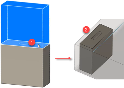
- End-face selected while Selection type is set to Planar face.
- Selected face is pointing upward in resulting nest.
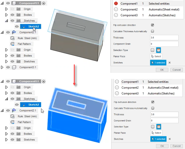
Sketches: Instead of selecting a body or planar face, you can select a sketch. An example of when you might want to do this would be if you want a part to be nested on an area slightly bigger than the part itself. This is sometimes done so that once the slightly bigger area is cut, it can be machined down to the exact size of the part with a better finish than would have been achieved with water- or plasma-cutting. In this case, you select the component in the list, set it to Sketch, and assign a sketch as the bigger area that will be cut and machined.
In this example, a sketch slightly bigger than the sample box is used. When it is selected, Fusion shows the extra area around the object that will be nested.
