Generate a Turning Thread toolpath
On the Manufacture workspace toolbar, click the Turning tab > Turning > Turning Thread
 .
.The Thread dialog opens.
On the Tool tab, click Select to pick a tool. If you have not created a tool to use, in the left panel of the Tool Library dialog, pick a tool from the Fusion Library, the Turning Tools library.
Tip: Select an OD or ID thread tool for this type of toolpath.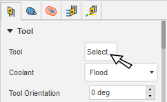
In the Tool Settings group, select a Spindle Rotation option.
Forward (clockwise) and Reverse (counter-clockwise) are relative to the main spindle while looking from behind the chuck. Ensure the spindle rotates towards the insert on the tool.
Note: This setting changes only the spindle direction and does not affect the tool orientation. Visually confirm simulation results and check the spindle M codes in the post-processed output before running code on a CNC machine.On the Geometry tab, select a Definition Method:
- Manual: Lets you enter values to manually define the thread geometry.
- Automatic: Lets you select Fusion-generated threads and detects values to define the thread geometry automatically.
- Standard: Lets you choose thread parameters from predefined options. Some values, like Thread Pitch and Major Diameter, are automatically populated based on the selected option from the drop-down lists.
With Thread Faces active, on the canvas, select the cylindrical face where you want to create the Thread toolpath.
Depending on you selected Definition Method, set the various Thread options.
Set the Confinement parameters to control the starting point and ending point for the threading toolpath in Z.
On the Radii tab, specify the Clearance radius.
On the Passes tab, select the Infeed Mode to specify how the tool enters for the depth cuts.
(Optional) To output the threading motion as a machine G-code canned cycle, select Use Cycle.
Note: It may require postprocessor modifications specific to your machine control.In the Depths of Cut group, adjust the depth of the First Pass.
(Optional) To repeat the final stepdown to remove any material that is leftover because of possible tool deflection, select the Spring Pass checkbox.
Click OK.
The toolpath is generated and displays on the canvas.
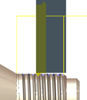
Turning a thread on the outside diameter of the part.