Activity 1: Create dimensions
In this activity, you:
- Save the drawing.
- Create dimensions.
- Create a dimension break.
Prerequisites
- Fusion is started.
- Data file location: Samples > Basic Training > 08 - Drawings > Connector_Joint_Drawing.
Steps
Save the Drawing.
With the Connector_Joint_Drawing design open, do the following:
If the drawing is "Read Only" (indicated in the title bar), click File > Save As.
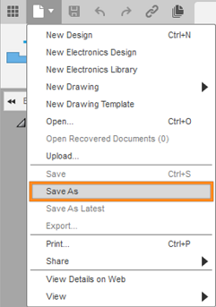
The Save as command is located under the File drop-down list.
Note: Even if a drawing is not "Read Only," you may wish to use the Save As command to preserve the original version of the drawing.(Optional) Create a new Project to store your training drawings and models. Click + Project to do so, specify the project name, and press
Enter. After a short pause, the new project becomes the active project, and a blank file list appears on the right side of the Save dialog.(Optional) Create a new folder within the project to store your training drawings and models. Click + Folder to do so, specify a folder name, and press
Enter. Double-click the new folder to make it the current file saving location.Click Save.
Initiate the Dimension command.
The Dimension command creates linear, aligned, angular, radius, and diameter dimensions based on the geometry you select in a drawing view. You select points, edges, or existing dimensions, then place the dimension on the sheet. The most appropriate dimension type is created automatically.
- From the Dimensions toolbar, select Dimension.
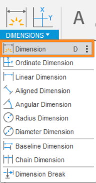
The Dimension command is located under the Dimension drop-down list.
Create the first dimension.
With the dimension tool active:
Select the first edge of the top view (as shown in the image below).
Select the second edge of the top view (as shown in the image below).
Place the dimension to the right of the view (as shown in the image below).
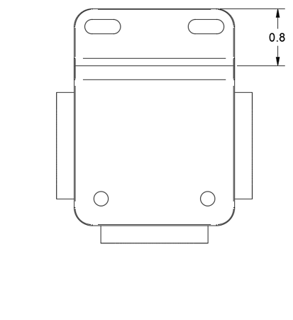
A Linear Dimension is created.
Create the second dimension.
With the dimension tool still active:
Select the edge of the bottom right circle (as shown in the image below).
Place the dimension to the right of the view (as shown in the image below).
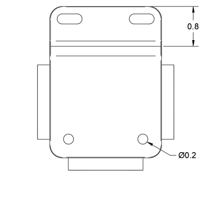
A Diameter Dimension is created.
Create the third dimension.
With the dimension tool still active:
Select the edge of the bottom left corner (as shown in the image below).
Place the dimension to the left of the view (as shown in the image below).
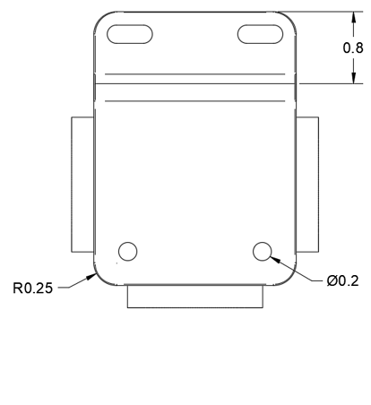
A Radial Dimension is created.
Create the fourth dimension.
With the dimension tool still active:
Select the center point of the bottom left circle (as shown in the image below).
Select the center point of the bottom right circle (as shown in the image below).
Place the dimension below the view (as shown in the image below).
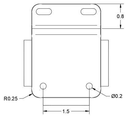
A Linear Dimension is created.
Create the fifth dimension.
With the dimension tool still active:
Select the first edge on the left (as shown in the image below).
Select the second edge on the right (as shown in the image below).
Place the dimension below the linear dimension below the view (as shown in the image below).
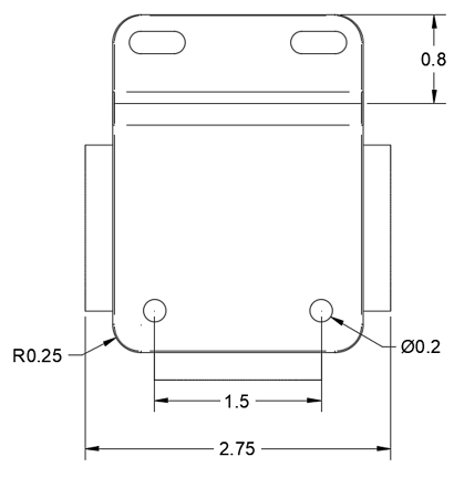
A Linear Dimension is created.
Create a Dimension Break.
The Dimension Break command creates a break in a dimension line or leader line where it intersects another dimension line or leader line.
From the Dimensions toolbar, select Dimension Break.
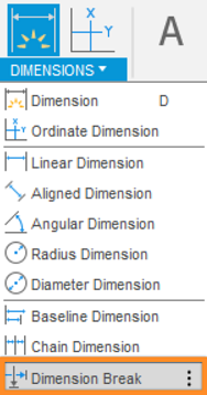
The Dimension Break command is located under the Dimension drop-down list.
Select the last linear dimension you created (2.75).

The Dimension Break dialog and selected dimension.
Click OK.
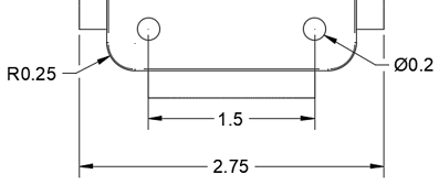
The Dimension Break is created.
This is the top view with all the dimensions and the dimension break.
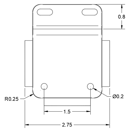
All dimensions in place.
Activity 1 summary
In this activity, you:
- Saved the drawing to a personal folder.
- Created linear, radial, and diameter dimensions.
- Created a dimension break.