Arrange objects
The Arrange command moves selected objects into an XY grid or circular formation. Arrange is available in both the Schematic and 2D PCB contextual workspaces. The dialog remembers the last values used except for spacing. Whenever a value is changed, remember to press Enter to preview the effect of the new value.
Rectangular formation

- With a schematic or board open, select the objects to arrange and click Modify > Arrange
 .
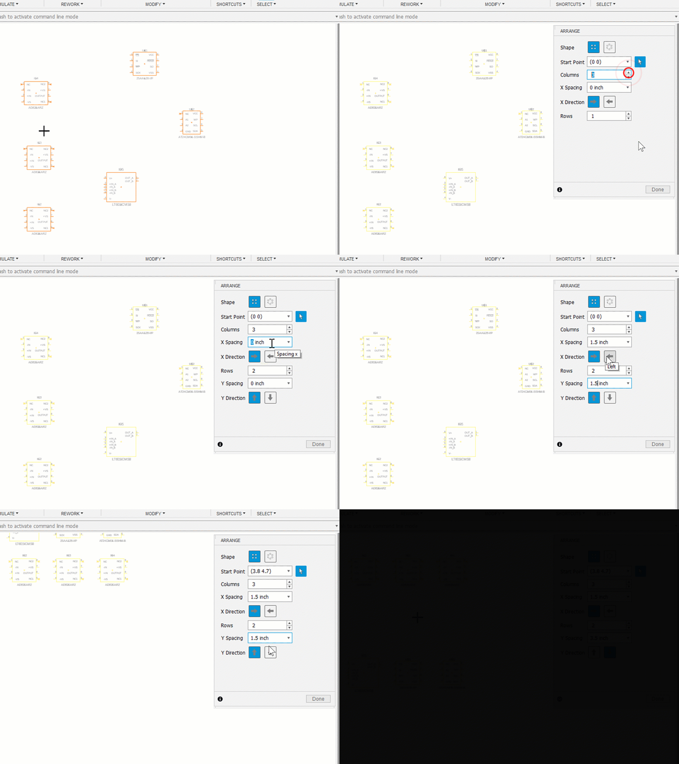
. - In the Arrange dialog for Shape, click rectangular
 . The options display progressively as you enter values.
 - Click in the canvas to specify the start point or use the dialog option.
- Specify the number of columns, X spacing, and X direction.
- Specify the number of rows, Y spacing, and Y direction.
- Continue to refine the formation either by clicking in the canvas or changing a dialog value and pressing Enter.
- Click Done when ready to accept the formation and location.
Circular formation

- With a schematic or board open, select object to pattern and click Modify > Arrange
 .
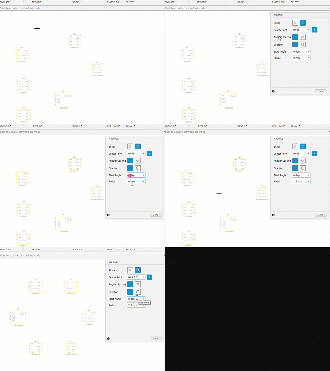
. - For Shape select circular
 . The options display progressively as you enter values.
 - Specify the Center Point using the dialog values or by clicking in the canvas.
- For Angular Spacing, specify Full or Angle. If Angle, specify the Total Angle the formation will populate.
- Specify the Direction, counterclockwise or clockwise.
- Specify the Start angle and radius.
- Continue to refine the formation either by clicking in the canvas or changing a dialog value.
- Click Done when ready to accept the formation and location.