Create a new footprint
There are two ways to create a new footprint. One way is to draw the footprint, the other way is to import a footprint that matches your needs.
Drawing a footprint
- With a library open, click New Footprint
 .
. - Provide a name for the footprint.
- Use DRAW commands to draw the footprint's accurate shape and size.
- Put silkscreen data on layer 21, SilkscreenTop.
- Put additional graphical information for documentation output on layer 51, DocumentTop.
- Draw restricted areas for the Autorouter, if needed, on layers 41, RestrictTop, 42, RestrictBottom, or 43, RestrictVias, or on layers 39, ComponentExcludeTop, or 40, ComponentExcludeBottom, by using the commands CIRCLE, RECT, or POLYGON SHAPE.
- Add mounting holes using the Hole (NPTH) command, if needed.
- Use one of the following commands to place pads:
- SMD Pad
- PTH Pad
- SMD Pad Array
- PTH Pad Array
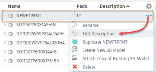
- In the Content Manager, right-click the footprint row and click Edit Description. Enter a description to complete the footprint.

Import an existing footprint
- With a library open, click New Footprint
 .
. - In the Add Footprint dialog, click Import.
- In the Import dialog, locate and select the component footprint you want to import. You can open the Library Manager from this dialog and select other libraries from which to import a footprint.
- To include the 3D package for the footprint, select Import connected 3D Package and click OK to import the footprint with its 3D model.
Place pads (though-hole contacts) or surface mounted device (SMD) contact areas with the following commands, which are only available in the Footprint Editor.
PAD
Place the pad of a conventional (through-hole) component. The pad comes with a plated-through drill that goes through all signal layers. The pad shape can be round, square, octagon, long, offset or slot in the outer signal layers. In the inner signal layers pads are always round.
SMD
Place a surface-mounted device (SMD) pad. You can change the name of the pads or SMDs with the NAME command.
Use the LINE, ARC, etc. commands to draw
- the symbol for the silkscreen on layer 21, SilkscreenTop,
- additional graphical information for the documentation print into layer 51, DocumentTop.
Draw restricted areas for the Autorouter, if needed, in layers 41, RestrictTop, 42, RestrictBottom, or 43, RestrictVias, or in layers 39, ComponentExcludeTop, or 40, ComponentExcludeBottom, by using the commands CIRCLE, RECT, or POLYGON.
Place mounting holes with the HOLE command, if needed.
Use the TEXT command to place
- the string
>NAMEin layer 25, NamesTop, serving as a text variable containing the name of the component. - the string
>VALUEin layer 27, ValuesTop, serving as a text variable containing the value of the component.
Use the DESCRIPTION command to add a description for the Footprint. HTML text format can be used for this.