Work with a new schematic
Create a schematic diagram and add components to it. You can use the schematic later to create a circuit board.
Create a schematic
- In Fusion, click File > New Electronics Design.
- Click New Schematic
 on the Electronics toolbar. A blank canvas opens so you can start creating your schematic.
 - Save your file.
Make sure the grid is set to 0.1 inch
Always use the default grid value of 0.1 inch when you create a schematic. Otherwise, the connections in your schematic might not transfer well to a circuit board. Do not change this value.
Click Grid Settings
 on the Schematic toolbar.
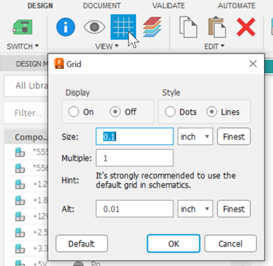
In the Grid dialog, make sure Size is set to 0.1 inch.
Add component libraries with the Library Manager
Use the Library Manager to add any component libraries you will need for your schematic.
Click Place component
 on the Schematic toolbar. The Place panel expands and displays available components on your computer.
Click Open Library Manager
 to the right of the libraries dropdown. The Library Manager opens; there are three columns.
Filters: Use filter criteria to refine the search for the library you want to use.
- Status: Choose from what is In use or Not in use in the active design.
- Source: Limit the data sources in which to search.
- Updates: Limit libraries with available updates.
- Used in: Limit the display to components already in use in the current design.
Results: Displays the libraries matching the filter criteria.
Details: Provides information about the selected library, such as name, folder, and whether it is a local or managed library. Additional information displays when available.
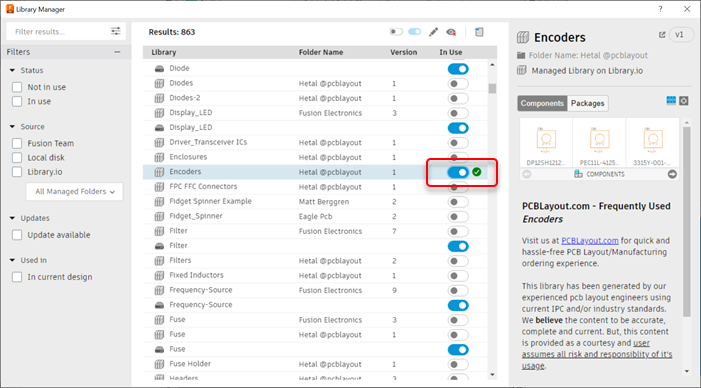
Toggle the In Use setting for any libraries you think you might need. When the library completes the download a confirmation badge (circle with check mark) displays. The library is enabled and can now be used in your designs.
Repeat for any other libraries you want to add.
Place a component in your schematic
Click Place component
 on the Schematic toolbar.
Find the component you want in the Place panel and double-click it.
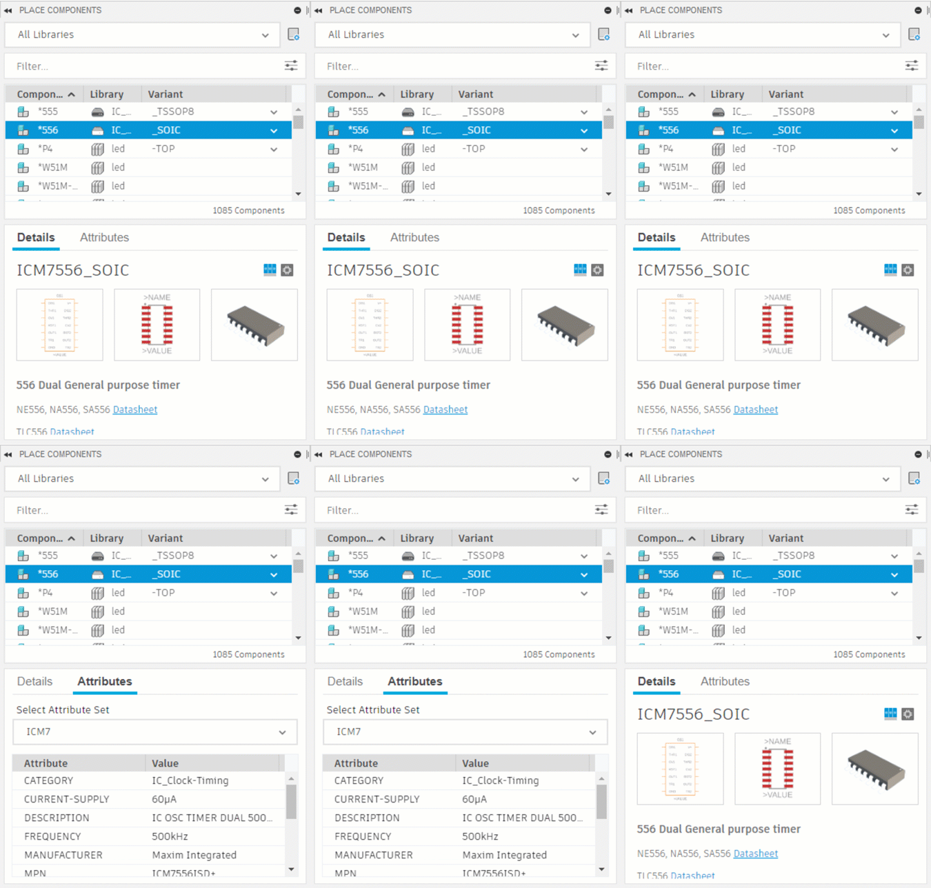
The mouse pointer changes into a cross, and an image of the component you are placing follows the pointer as you mouse over the canvas.

Mouse pointer
Component being placed
The origin is indicated by a stationary cross in the canvas.

To change the orientation of the component before you insert it:
- Right-click to rotate the component by 90 degrees
- Middle-click to mirror the component (flip it left to right)
Mouse over the spot where you want to place the component.
The toolbar shows the coordinates of the mouse pointer.
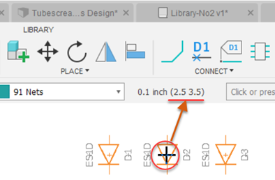
Click where you want to place the component.
Optional: continue clicking to place more copies of the same component.
Click OK or press Esc to return to the Place panel so you can place other components, such as resistors, capacitors, 555 timers, LEDs, and so on.
Connect the components
Create connections between components using Net.
- Click Net
 on the Schematic toolbar.
 - Enter a name for the connection in the command line box.

Any subsequent connections given the same name will be grouped together as one. If you do not enter a name, Electronics will create one for you automatically.
- Optional: In the NET dialog that opens, change connection properties such as Bend, Style, and so on.
- Mouse over a spot where you want to start drawing a connection.
A circle highlights a pin, if one is available.
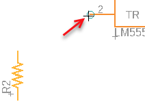
- Click to start drawing the connection.
- As you move the mouse, you can click to create segments in the line.
- Move the mouse pointer to an end-point.
A circle highlights the available end-point.
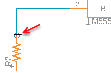
- Click a pin where you want to finish the connection.
If you want to finish the line without using an end-point, double-click, and make sure to connect the line to something later.
- Repeat for other connections in your schematic.
If you cross two lines, they are treated as separate connections.

If you join a line to another by clicking on it, a junction point is created and the lines are considered to be part of the same connection.

Modify NET connections
When connections are made, relationships between components are created, and you should avoid modifying them. However, there are still some things you can do to change your connections. Enable Select ![]() on the Schematic toolbar first.
on the Schematic toolbar first.
- To remove a segment, click the segment, then press Delete.
- To remove a connection point, delete the segments connected to it. Use NET to draw in a new connection or line segment.
- To resize a connection, click and drag its end-point or joint.
- To rename a connection, select it, and enter a new name in the Name box of the Inspector panel.
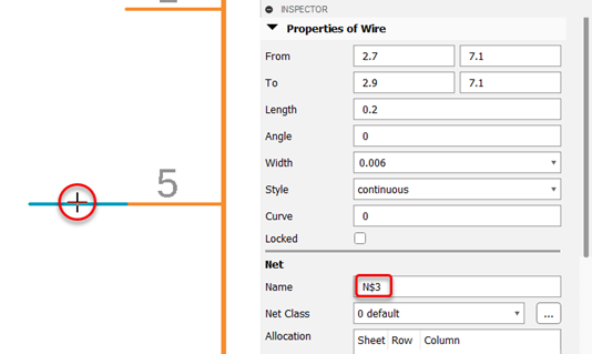
If other connections have the same name, the new name will be applied to all of them.
Move multiple items in the schematic
- Click Select > Group on the Schematic toolbar.
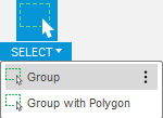
- Marquee select (drag around) the items you want to move.
- Click and drag the origin
 one of the items to move the selected items as a group.
Video: Demonstration of how to create a schematic
Key concepts:
- Placing and moving components
- Defining connections
- Adding power
- Assigning values to components
Length: 5:34