Create a new symbol
With a library open, click New Symbol
 .
.Provide a name for the symbol.
Use tools in the DRAW panel or commands LINE, ARC, etc. to create the schematic representation of the symbol on layer 94, Symbols.
To add pins, first ensure that the drawing grid is turned on and set to 0.1 inch or 2.54 mm.
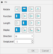
Enter PIN in the command line and use controls on the following dialog:

A pin appears beside the cursor as you move around the symbol diagram. Right-click to rotate the pin in 90-degree steps, and use the other controls in the dialog as follows:
- Change the pin function or length
- Set the Display, which specifies the contents of a label
- Set the Direction, which is the logical direction of signal flow
- Set the SwapLevel, as described below
SwapLevel setting of 0 means that the pin cannot be used for the same purpose as another pin in the same symbol. Any integer above 0 means that the pin can be used for the same purpose as other pins of the same Swaplevel in the same symbol. For example, if a chip has multiple instances of the same gate, you can connect signals to any set of pins for such a gate and get the same function. The pins of each identical gate can use the same set of SwapLevel settings.
Pins can be swapped in the schematic or in the board with the PINSWAP command.
You can use the TEXT command to place the following items:
- the string >NAME in layer 25, NamesTop, serving as a text variable containing the name of the component,
- the string >VALUE in layer 27, ValuesTop, serving as a text variable containing the value of the component.