Create a PCB from a sketch
This feature brings more automation to the Electronics design process by creating links between a printed circuit board (PCB) profile sketch, 3D drawing, and 2D board design. Changes to the sketch or the board design can be pushed directly to the 3D model.
Sample workflow
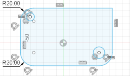
In the Fusion Design workspace, create a 2D sketch of a PCB, with precise dimensions and geometry. In the Sketch Palette, click Finish Sketch.
In the toolbar, click Create > Create PCB > Create Associative PCB.
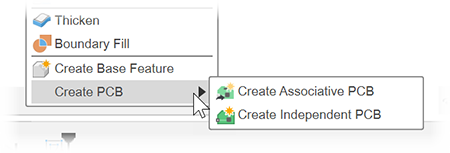
An associative PCB is linked to the sketch and can update when the sketch changes. Or, you can create an independent PCB which is not linked to the originating sketch.
A new 3D drawing opens, showing the board with a default thickness.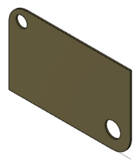
From the 3D drawing toolbar, click Modify > Push to 2D PCB.
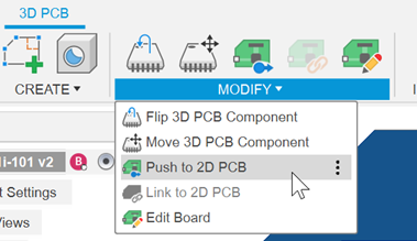
A new 2D PCB drawing is created, which you can use to add components to the board from a library.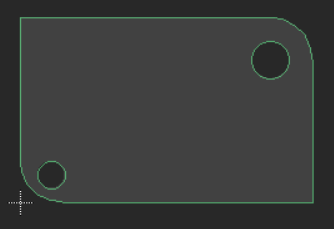
If you have an existing 2D PCB design, you can use the related command Modify > Link to 2D PCB.In the 2D PCB drawing, on the toolbar, you can click Switch > Push to 3D PCB to see how your 2D design looks with the 3D packages in place.
With these links created, you can proceed to update the sketch, if necessary, and add components to the 2D PCB. If you see a yellow triangular warning that the 3D PCB is out of sync with one of the other documents, click the warning to restore the sync.
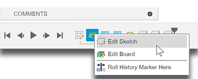
To edit the sketch or the board from the 3D model, in the timeline right-click the board node and select the item you want to edit.