Work with multi-part components
Components can consist of multiple parts to be represented with different symbols. A common example is an integrated circuit chip that contains multiple logic gates. This topic shows how to work with multiple parts in a schematic and in a component.

Create a multi-part schematic
Start a new design, click File > New Electronic Design.
In the Schematic toolbar, click Design > Place > Place Component
 . The Place panel expands for component selection.
If you know the library that has the component, select that library in the dropdown. Or, leave as All Libraries and use the filter option.
In the Filter... field, enter the component or library you are searching for.
Using the example animation above, enter IC_LOGIC in the filter field. Notice the list refines as you enter text. In the Component column, double-click the 74*32 component and move the cursor into the canvas. The component symbol is attached to the cursor.
Place gates in sequence by clicking the canvas. Optionally, right-click to rotate before placing or use the tools in the Add dialog. Note that as they are pasted, the symbols are named sequentially, such as IC1A, IC1B, etc.
Click OK in the Add dialog or press Esc to stop pasting.
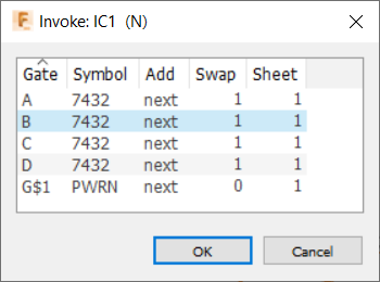
Click a gate origin point (typically, + at symbol center), then right-click > Invoke to examine symbol data.

Make any needed adjustments to the symbol attributes and click OK.
Create a multi-part component
In a library document, click New Component
 , and assign it a name.
To select a symbol from the current library, click Add
 and then OK; to get one from a different library, click New Symbol
  , then Import.
Select the part symbol from a library, then OK. The symbol is added to the current library.
To return to the Component creation process, click Components, then double-click the specific component to select it.
Click Add
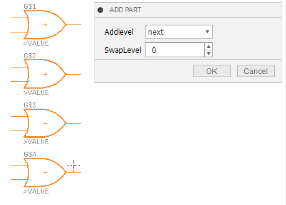
 , select newly added symbol, and paste several instances. The example below uses OR gates IC_Logic\7432. Note how the symbol numbers increment with each paste (G$1, G$2, etc.), and the ADD dialog with Addlevel and SwapLevel fields that you can use to set these values.
Click Done or press Esc to stop pasting.
To add a package and footprint to the component, in the Content Manager pane right-click and select New package, or New > Add local package > Import, to go to a different library.

In this example we add IC_Logic\DIL14. The footprint has 14 pads, suitable for accommodating the 12 pins in our 4 OR gates. As we add it to the current library, we must provide a name for this package variant.
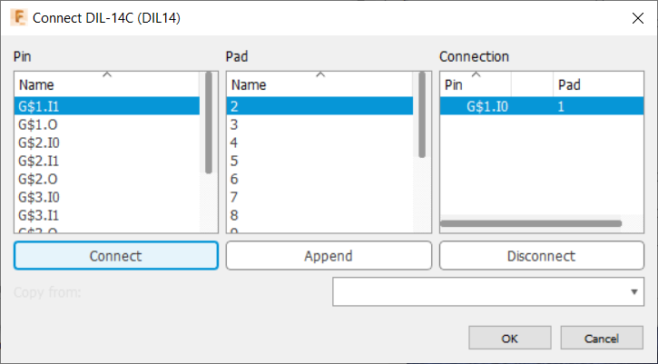
Click Connect to start assigning pins to pads, based on an available spec sheet, clicking Connect after each assignment.

When the connections are all made, click OK.