Multilayer board terms and examples
Core
The non-flexible kernel which is coated with copper on one or on both sides. Is represented by a * in the Layer Setup. For example 5*12: Layer 5 and 12 are the board's core.
Prepreg
Flexible glueing or isolating layer which is used in the manufacturing process of a multilayer board to press inner and outer layers onto each other. Is represented by a + in the Layer Setup. 1+2 tells us that layer 1 is a prepreg and combined with layer 2.
Layer stack
A pack of any number of layers consisting of cores and prepregs which are handled together in the current step of production.
Buried via
The production process of this via does not differ from a through (normal) via. The current layer stack will be drilled through completely. In the following production steps the already drilled vias can be covered (buried) by pressing further cores and prepregs on the current layer stack. If the via is not visible on the completed board we call it a buried via.This is represented by parenthesis, for example in 1+(2*15)+16 where the Buried Via goes from layer 2 to 15.
Blind via
A Blind via connects an outer layer with any inner layer but doesn't go through all copper layers. The specialty of a Blind via lies in the production process. The current layer stack is not drilled all through. The drill hole has a certain depth depending on the number of layers that should be allowed to be connected with each other. Blind vias have to follow a given ratio of depth to drill diameter. Please contact your board house to get information about this. This ratio has to be defined in the Sizes tab as Min. Blind Via Ratio.This is represented by brackets and the target layer marked by a colon before or after the bracket. The example [3:1+2+3*14+15+16] allows Blind vias from layer 1 to 3. Blind vias may be shorter than defined. In this example you are allowed to use vias from layer 1 to 2. The Autorouter is also allowed to use shorter Blind vias.
Micro via
The micro via is a special case of a Blind via. It has a maximum depth of one layer and a very small drill diameter.
Displaying vias
It makes sense to set the layer color of layer 18, Vias, to the background color (DISPLAY menu, Change, Color) if you are working with vias that have different lengths and shapes. In doing so it is possible to recognize layer affiliation.
Layer setup
Combining cores and prepregs allows many variants. In the following section some examples show the function of the Layer setup. Please read this paragraph entirely. Even if you intend to design a four layer board, for example, it is most advisable to read also all the other examples for a better understanding.
When defining your layer stack, always work from the surface layers toward the inner layers. For example, for a 4-layer board the correct stackup would use layers 1, 2, 15, and 16. Do not use 1, 2, 3, and 16. Always work from outside layers towards the inner layers.
4-layer board**
Example 1
- Layers 1, 2, 15 and 16 are used.
- Board structure: One core inside, outside prepregs.
- Connections: 1-2 (blind vias), 2-15 (buried vias) and 1-16 (through vias)
Setup expression
[2:(1+(2*15)+16)]
Explanation
| Expression | Description |
|---|---|
2*15 |
Layers 2 and 15 form the core. |
(2*15) |
Parentheses allow buried vias from 2 to 15. |
(1+(2*15)+16) |
On both sides of the core copper layers are pressed on with prepregs. The outer parentheses define continuous vias from 1-16. |
[2:(1+(2*15)+16)] |
In square brackets and separated by a colon blind vias are defined. Here from layer 1 to 2. |
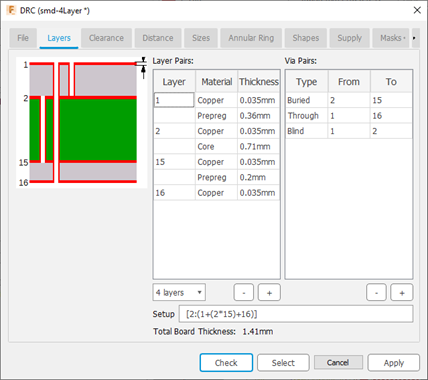
Blind vias have to keep a certain ratio of via depth to drill diameter. For this reason it is necessary to specify values for the layer thickness.These values are given by your board house! You are supposed to contact it in either case before starting the layout!
Type in the values in the Copper (thickness of copper layer) and Isolation (thickness of isolation layer) fields as shown in the image. The total thickness of the board is shown below the Copper and Isolation fields.
Example 2
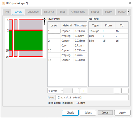
- Layers 1, 2, 15, and 16 are used.
- Board structure: One core inside, outside prepregs.
- Connections: 1-2, 15-16 (blind vias), 1-16 (through vias)
Setup expression
[2:(1+2*15+16):15]
Explanation
2*15 |
Layers 2 and 15 form the core. |
1+2*15+16 |
On both sides of the core copper layers are pressed on with prepregs. |
(1+2*15+16) |
The outer parentheses define through vias from 1-16. |
[2:(1+2*15+16):15] |
In square brackets and separated by a colon blind vias are defined. Here from layer 1 to 2 and 16 to 15. |
6-layer board
Example 3
- Layers 1, 2, 3, 14, 15, and 16 are used.
- Board structure: Two cores, prepregs outside.
- Connections: 2-3, 14-15 (buried vias), 1-16 (through vias)
Setup expression
(1+(2*3)+(14*15)+16)
Explanation
(2*3)+(14*15) |
Two cores with buried vias are pressed together. |
1+(2*3)+(14*15)+16 |
This layer stack is covered with outer layers 1 and 16 which are isolated with prepregs. |
(1+(2*3)+(14*15)+16) |
The whole expression in parentheses defines through vias from 1-16. |
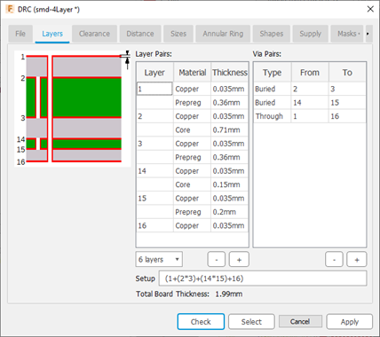
The values for layer thickness for copper and isolation used in these examples are fictive. Please contact your board house to get the allowed values.
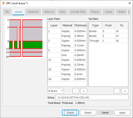
Example 4
- Layers 1, 2, 3, 14, 15, and 16 are used.
- Board structure: One core, on each side two prepregs.
- Connections: 3-14 (buried vias), 2-14 (blind vias in inner layer stack), 1-16 (through vias)
Setup expression
(1+[14:2+(3*14)+15]+16)
Explanation
2+(3*14)+15 |
The core with buried vias. One prepreg on each side. |
[14:2+(3*14)+15] |
Blind vias from layer 2 to 4. |
1+[14:2+(3*14)+15]+16 |
On this layer stack a prepreg on each side is pressed on. |
(1+[14:2+(3*14)+15]+16) |
Parentheses allow through vias from 1 to 16. |
8-layer board
Example 5
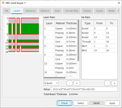
- Layers 1, 2, 3, 4, 13, 14, 15, and 16 are used.
- Board structure: Three cores, prepregs outside.
- Connections: 1-3, 14-16 (blind vias), 2-3, 4-13, 14-15 (buried vias), 1-16 (through vias).
Setup expression
[3:(1+(2*3)+(4*13)+(14*15)+16):14]
Explanation
(2*3)+(4*13)+(14*15) |
Three cores, each with buried vias, are pressed together and isolated with prepregs. |
1+(2*3)+(4*13)+(14*15)+16 |
Outer copper layers 1 and 16 which are isolated through prepregs are pressed onto this layer stack. |
(1+(2*3)+(4*13)+(14*15)+16) |
Parenthesis allow through vias from 1-16. |
[3:(1+(2*3)+(4*13)+(14*15)+16):14] |
Blind vias from 1-3 and 16-14. |
