SPICE simulation in the schematic
Use Simulation to verify circuit designs. SPICE (Simulation Program with Integrated Circuit Emphasis) is a program for the simulation of analog, digital and mixed mode electrical circuits. Operations can include a simple check to make sure all diodes are receiving the current they require based on chosen values, or verifying that the gain and frequency response of an analog amplifier match hand calculations.
Electronics includes a copy of ngspice, an open-source mixed-level/mixed-signal circuit simulator, based on Berkeley spice3f5.
ngspice supports Operating Point, Transient (time), AC (frequency), and DC Analysis types, full digital and mixed-signal simulation modes. You can simulate any valid SPICE circuit, which means all components in your schematic have been mapped to SPICE models, either primitive or model-based.
Electronics comes with a small library of simulation-ready parts called ngspice-simulation, which are library parts that have been pre-mapped to their proper SPICE types, and models have been provided, where applicable. This means you can easily create simulation-ready schematics with these parts. You can also make your own simulation-ready library parts, or setup your parts within an existing schematic, no matter what library they came from.
Digital simulation enables you to simulate digital circuits that make use of digital logic primitive gates, such as AND, OR, and NOT. There are many built-in digital primitives, and Fusion Electronics provides some of these mapped to library parts in the ngspice-digital shared library.
Simulate circuit performance with SPICE
Create a schematic using components from ngspice-digital and ngspice-simulation libraries. You can load these from the Available list, if necessary. The components in these libraries are already mapped to SPICE models, which is essential for accurate simulations.
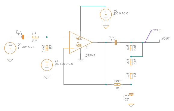
Assign appropriate values for resistance, capacitance, etc. to the components in your schematic. Add a Voltage Probe or Phase Probe in a logical place, for example:
- Click Voltage Probe

- Click location in circuit to place the probe.
- Lengthen the VOUT arrow.
Sample schematic

- Click Voltage Probe
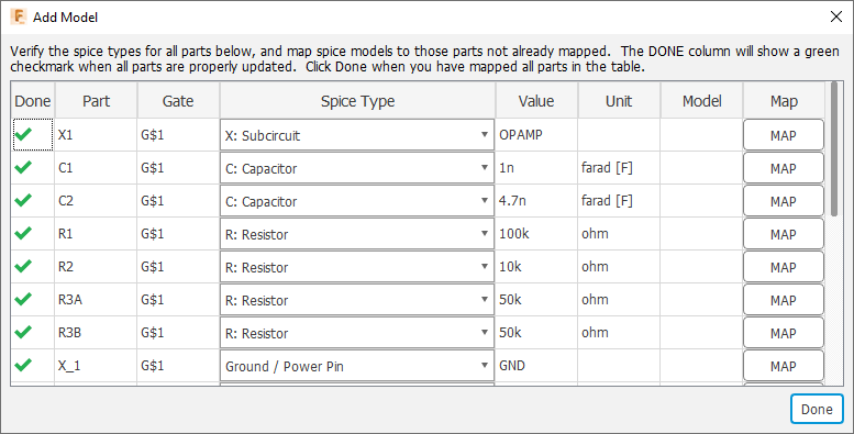
Select the entire circuit design by drawing a rectangle around it, then click SIMULATE > Add Model. When asked if you want to convert any Ground (GND) parts to SPICE ground, click Yes.

The Add Model table shows all the circuit components, with a green check mark in the Done column. In this table you can review and correct any values for components. If you had used any component that was not mapped to a SPICE model, you would see an alert icon
 , and you could click the Map button to start the process of mapping the component to SPICE.
In the ribbon, click Simulate
 .
.
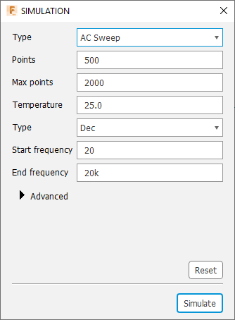
In the SIMULATION dialog, set the Type value (Operating Point, DC Sweep, AC Sweep, or Transient). In most cases, leave other options at default values.
In the dialog, click Simulate. When the simulation is finished, you see several output graphs. In this example of an AC Sweep, the Voltage graph is the most useful.

Note that you can use the gear icon in the upper right to switch the frequency display from logarithmic to linear.