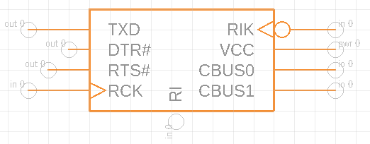
Use Paste Pins for pin setup
This labor-saving operation is especially useful for speeding up the process of pin configuration on a large integrated circuit (IC) chip. First set up the pins in the Symbol Editor, then arrange them around the edges of the chip symbol. Two different procedures are described below.
Copy pin names from a datasheet
This is the simplest operation, providing only the pin names.
In a PDF copy of the datasheet, Alt-Select the desired pin names from a table column.
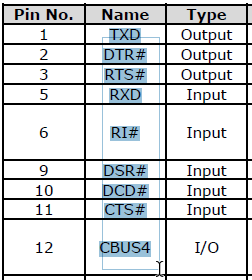
In the Symbol Editor, click Edit > Paste Pins
 to insert the named pins in a single column.
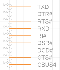
Use the Inspector panel to manually modify pin data such as direction and function, based on information in the datasheet.
Use Draw tools to group, move, rotate, mirror, and align pins as required, placing them around the sides of the chip.
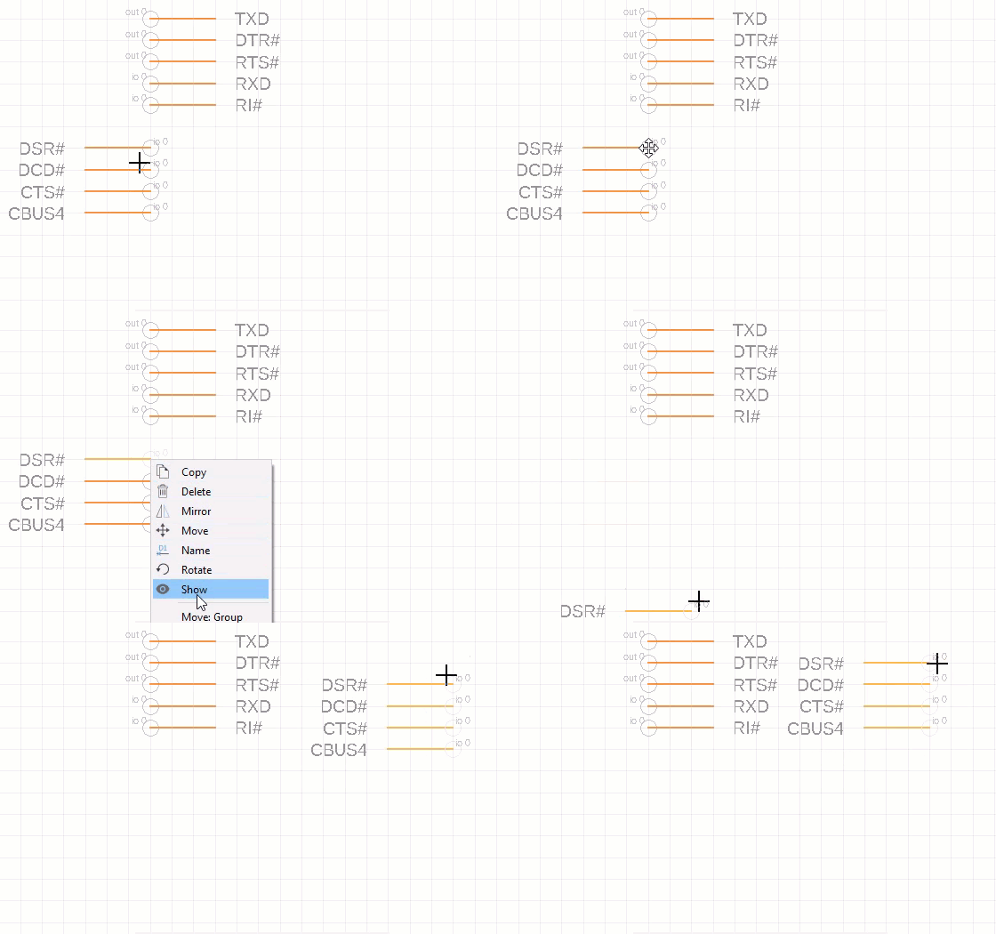
Use the Line tool to draw a rectangle that represents the chip and connects the pins.
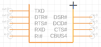
Provide pin names, direction, and other data in an Excel spreadsheet
With this method, you can supply pin names along with other values as follows:
- Pin length: point, short, middle, long
- Direction: nc, in, out, io, oc, pwr, pas, hiz, sup
- Function (for digital logic signals): none, dot, clk, dotclk
Create an Excel spreadsheet with Name in column 1, followed by any other columns in use: Length, Direction, Function.
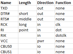
Enter data into the cells, using the lowercase strings that appear in the INSPECTOR panel, also listed in bullets above this procedure.
Copy the table, including the heading row.
In the Symbol Editor, click Edit > Paste Pins
 to insert pins in a single column, noting that any set Length, Direction, and Function values are included.
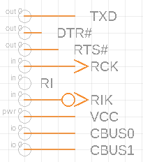
Use Draw tools to group, move, rotate, mirror, and align pins as required, placing them around the sides of the chip.
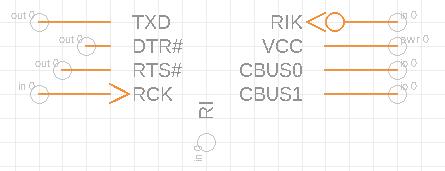
Use the Line tool to draw a rectangle that represents the chip and connects the pins.
