Activity: Manual Routing Practice
In this activity, you:
- Use the following options in the Route Manual dialog: Routing, Loop Remove, Trace Bend, Trace Width.
- Use the Unroute to return the signal to its original unrouted state.
- Use many useful shortcuts while manually routing.
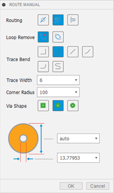
Route Manual dialog.
Prerequisites
- Data file location: Electronics Samples > One Dimensional Pong.
Steps
Open the One_Dimensional_Pong 2D PCB from the Electronics Samples > One Dimensional Pong folder and save it to a project and folder of your choice.
- Click Show Data Panel
 , if necessary, and navigate to the Home view to show the list of projects.
 - Click Samples > Electronics Samples > One Dimensional Pong and open the One_Dimensional_Pong 2D PCB.
- Click File
 > Save as and save the design with the name One_Dimensional_Pong in the project or folder of your choice.
- Click Show Data Panel
Click Design > View > Grid Settings
 and set the Size units to Mil.
Delete routes shown in the video with the Unroute tool so you can re-create routes.
Click Design > Unroute > Unroute
 .
.In Unroute dialog, click Connection
 .
.Click the routes shown in the video.

Use the Ignore Violators option to create a route. Ignore Violators allows you to violate routing rules like crossing over other routes. Normally, you do not want to use this option but sometimes you will need to create a route using this option and then fix the violation.
In the PCB workspace, click Design > Route > Route Manual
 .
.At the bottom of the canvas, on the toolbar select Ignore Violators
 from drop-down list.
Click a signal between the components RN4 and U1. Notice that the signal is being converted into a trace. You are able to overlap existing traces, pads, or objects that generate a Design Rule Check violation. Click to start, end, and create a segment of the trace.
Create a second trace between the components RN4 and U1. Create a segment of the trace that crosses the first trace you made. As shown in the video.

Use the Walkaround Violators option to create a route. The Walkaround Violators routing option is the default selection. When using Walk Around Obstacle, routing avoids overlap violations and follows the clearance and width routing preferences defined in the Design Rule Checker.
- Delete routes that you created in the previous step with the Unroute , so you can re-create routes.
- Click Design > Route > Route Manual .
- At the bottom of the canvas on the toolbar select Walkaround Violators
 from drop-down list.
 - Create several routes between the components RN4 and U1. When you create segments of a route, the segment being created goes around obstacles preventing violations in routing rules.
- Use the following shortcuts while practicing making routes.
- Click to create a segment of the trace.
- Right-click to use the mirrored bend style.
- Backspace to delete the last segment created, before the route has finished.
- Esc to exit the Manual Route tool.
- Delete routes that you created in the previous step with the Unroute
Use the Push and Shove option to create a route. This option moves existing traces making space to route the selected signal.
Delete routes that you created in the previous step with the Unroute
, so you can re-create routes.Click Design > Route > Route Manual
.At the bottom of the canvas on the toolbar select Push Violators
 from the drop-down list.
Create several routes between the components RN4 and U1. When you create segments of a route, the segment being created will push other obstacles out of the way preventing violations in routing rules.
Note: A yellow semi-circle appears when you can no longer push and shove in the direction you are going.
Change the Trace bend option when creating a route. The 45 degree bend is the default and most used. However, different bends are often necessary. The Corner Radius setting influences the size of three of the trace bend types.
- Delete routes that you created in the previous step with the Unroute , so you can re-create routes.
- Click Design > Route > Route Manual .
- Select Walkaround Violators .
- Start to create a route between the components RN4 and U1. As you create a segment, change the trace bend type. Hold Ctrl and Right-click to cycle through the bend styles.
- Delete routes that you created in the previous step with the Unroute
Change the Trace Width option when creating a route. The width of the trace may need to be changed based on the current passing through the trace.
- Delete routes that you created in the previous step with the Unroute , so you can re-create routes.
- Click Design Route > Route Manual .
- Select Walkaround Violators .
- Start to create a route between the components RN4 and U1. As you create a segment, change the trace width to 12 mil in Trace Width box in the Route Manual dialog.
- Continue to make the segment.
- Delete routes that you created in the previous step with the Unroute
Use the Via option when creating a route. A via is used to transition a signal being routed between available signal layers. The Via option allows you to define the shape of the via. The default option is round.
Delete routes that you created in the previous step with the Unroute
, so you can re-create routes.Click Design Route > Route Manual
.Select Walkaround Violators
.Begin routing a signal between RN4 and U1. As you route the signal press the Space. The via will now appear on your pointer.
Click to place the via.
Continue routing on the transitioned layer.
Note: If your design has a layer stack up of over two layers, change layers by selecting the Middle mouse button. This option allows you to select the specific signal layering the Layer dialog to continue routing after placing the via.
Use the Loop Remove option to edit a route. The loop options allow you to preserve or remove when routing an existing trace. With the loop remove option selected you can reroute an existing trace and the original trace is deleted.
- Delete routes that you created in the previous step with the Unroute , so you can re-create routes.
- Click Design > Route > Route Manual .
- Select Walkaround Violators .
- Click Loop Preserve
 in the Route Manual dialog.
 - Select one of the signals and completely route it.
- With the route completed, click any segment of the routed signal. See that a new route will stem from the original trace.
- Click to end the routing. Notice that the looped segment will remain.
- Click Loop Remove
 in the Route Manual dialog.
 - Create another trace between the same start and endpoints that you did before. See how one of the traces is being modified suggesting it will be deleted.
- Delete routes that you created in the previous step with the Unroute
Activity summary
In this activity, you used manual routing of signals with Routing, Loop Remove, Trace Bend, Trace Width options. Later you used the Unroute to return the signal to its original unrouted state.