Milling
A subtractive manufacturing method that enables you to include milling constraints in a generative study.
Select this option to generate outcomes which can be manufactured using 3- or 5-axis milling operations.
You can define different milling configurations in the Manufacturing dialog.
To define a milling configuration, specify:
Milling type: 3-axis or 5-axis.
In 3-axis milling, a part is machined along the three axes of the global coordinate system: X, Y, and Z.
In 5-axis milling, a part or the cutting tool moves along five different axes simultaneously. It moves across the linear axes: X, Y, and Z rotates about the axes: A and B.
Tool Direction. It enables you to set tool orientations for 3-axis milling operation. The tool direction is oriented with reference to the Global Coordinate System.
| Tool direction button... | Used... |
|---|---|
X+ 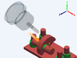 |
to orient the tool in the direction parallel to the X axis of the triad and pointing to the positive end of the X axis. |
Y+ 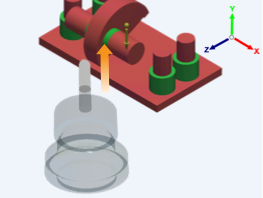 |
to orient the tool in the direction parallel to the Y axis of the triad and pointing to the positive end of the Y axis. |
Z+ 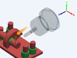 |
to orient the tool in the direction parallel to the Z axis of the triad and pointing to the positive end of the Z axis. |
X- 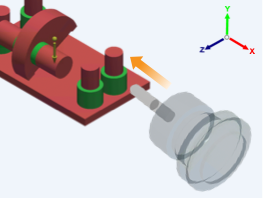 |
to orient the tool in the direction parallel to the X axis of the triad and pointing to the negative end of the X axis. |
Y- 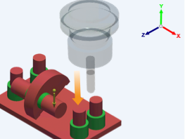 |
to orient the tool in the direction parallel to the Y axis of the triad and pointing to the negative end of the Y axis. |
Z- 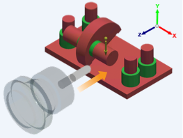 |
to orient the tool in the direction parallel to the Z axis of the triad and pointing to the negative end of the Z axis. |
Minimum Tool Diameter. It is a diameter of the smallest cutting toll considered for a milling operation. See point no. 1 below:
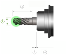 Note: Sizes of outcome features, like pockets, slots, and fillets, depend on the minimum tool diameter. While many tools may be used in the manufacturing process, enter the diameter of the smallest tool you plan to use.
Tool Shoulder Length. It is the length of the part of the tool considered in the setup of the generative study. See point no. 2 below:
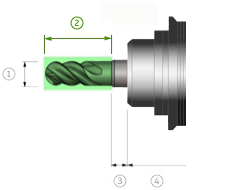
Head Diameter. It is a diameter of a simplified head that contains the shaft and holder. See point no. 5 below:
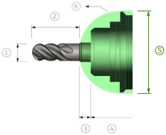 Note: For shape generation, an infinite length of the head is considered. It is assumed that the shaft and holder are within a simplified hemisphere defined by the head diameter.