Activity 2: Create features for the threaded mount
In this activity, you open the sample file Threaded_Mount and save it to a personal folder. You use the Hole tool to create four counterbore holes, the Shell tool to remove unwanted material, the Web tool to add support, and the Thread tool to create threading on the shaft of a mount model.
You start with the timeline rolled back to exclude existing features, temporarily, so your new features don’t impact these existing ones.
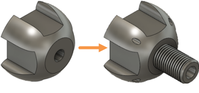
Threaded_Mount starting model (left), and with added features (right)
Prerequisites
- Fusion is started
- Data file location: Samples > Basic Training > 04-Modeling > Threaded_Mount.f3d
Steps
Open the sample file, Threaded_Mount, and save it to a personal project.
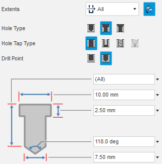
Note: Refer to Activity 1 for detailed instructions.Create 4 counterbore holes that extend all the way through the mount using the four points on the corners of the Hole Feature sketch. Set the diameter to 7.5 mm, the tip angle to 118 degrees, the counterbore depth to 2.5 mm and the counterbore diameter to 10 mm.
In the Browser, expand the Sketches folder, then click the visibility icon
 associated with Hole Feature, to make the Hole Feature sketch visible.
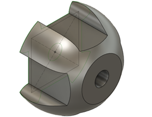 Note: The Hole Feature sketch appears on the bottom face of the mount.
Click Design > Solid > Create > Hole
 to activate the Hole tool.
Select the corners of the sketch as the Sketch Points for the holes.
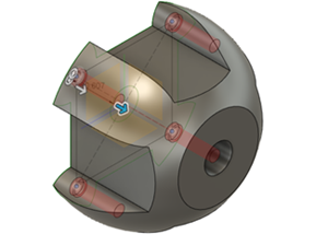
In the Hole dialog, set the Extents to All and the Hole Type to Counterbore, then match the dimensions of the drill to those in the image:
Ensure the hole tool is going in the right direction, and click Flip Direction
 to correct it, if necessary.
Click OK to complete the tool and close the Hole dialog.
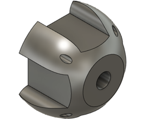
Apply an Inside shell to the bottom face of the model, with a Thickness of 2.5 mm.
Click Design > Solid > Modify > Shell
 to activate the Shell tool.
Rotate the model so you can see the underside, then click on the bottom face of the body to select it as the Face/Body to remove.
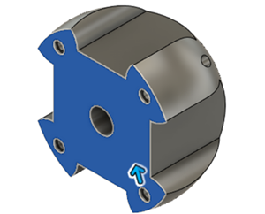
Type 2.5 to set the Inside Thickness to 2.5 mm.
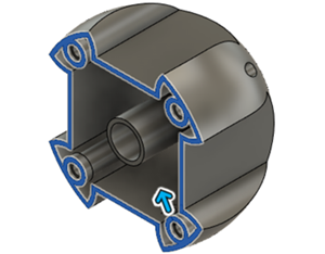
Click OK to complete the operation and close the Shell dialog.
Note: Now that you have created the shell, you can include the rest of the features in the timeline.
Make the Web Sketch visible.
Drag the timeline marker to the end of the timeline to include all the features of the model.
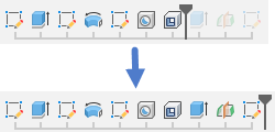
In the Browser, expand the Sketches folder and make the Web Feature visible.
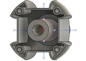
Create a 2.5 mm thick Web feature to support the inside of the mount, using the 4 sketch lines that intersect with the four sides of the model.
Click Design > Solid > Create > Web)
 to activate the Web tool.
Click on the four sketch lines in the canvas to select them as the Curves
In the Web dialog, confirm that Thickness Options is Symmetric, and Depth Options is To Next, then set the Thickness to 2.5 mm.
Note: If the web doesn’t appear to be correct, click Flip Direction and the web preview will appear.
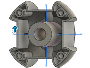
In the Web dialog, click OK to complete the operation and close the dialog.
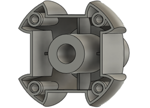
Apply a Chamfer to the end of the shaft protruding through the model. Set the Distance to 3 mm and the Type to Equal distance.
Click the Home View to rotate the model so you can see the shaft.
Click (Design > Solid > Modify > Chamfer
 to activate the Chamfer tool.
In the Chamfer dialog, set the Chamfer Type to Equal distance
Click on the circular edge on the end of the cylindrical protrusion, to select it as the Edge.
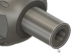
Type 3 to set the Distance to 3 mm in the chamfer dialog.
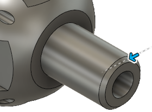
Click OK to complete the tool and close the Chamfer dialog
Model threading along the Full Length of the cylindrical face, using ISO Metric profile for the Thread Type, and the M39x4 for the Designation.
Click Design > Solid > Create > Thread
 to activate the Thread tool.
Click on the cylindrical face of the shaft, to select it as the Face.
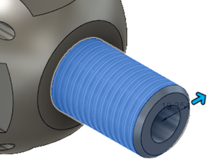
In the Thread dialog, select Modeled and Full Length, to create the threads as modeled geometry that extend along the shaft to the chamfered edge.
Note: The Modeled option cuts actual thread into the geometry.Set the Thread Type to ISO Metric profile, the Size to 39.0 mm, the Designation to M39x4, the Class to 6g, and the Direction to Right hand.
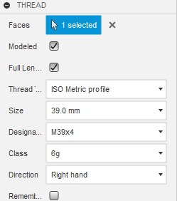
Click OK to complete the tool and close the Thread dialog.
Go to Activity 5 to check your modifications.
Activity 2 summary
In this activity, you created 4 counterbore holes on the mount. You shelled the model to remove unnecessary material, then added support to the underside. You added a chamfer to the circular edge of the shaft, then you added threads to the shaft.
You accomplished this task using the following tools:
- Hole
- Shell
- Web
- Chamfer
- Thread