Activity 2: Create the fan blades
In this activity, you use sketch lines to create a single blade surface, and from the single blade surface you create 8 solid fan blades around the hub. To create the fan blades, you
Create a single blade lofted surface from simple sketch lines
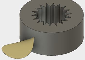
Trim the outer edge of the blade using a spline sketch, to form a rounded shape
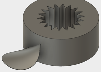
Thicken the blade surface to create a solid body
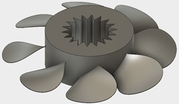
Pattern the blade solid body to create 8 instances around the hub.
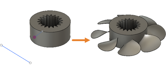
Fan hub with blade sketches (left), and fan hub with blades (right)
Prerequisites
- Activity 1 is complete.
Steps
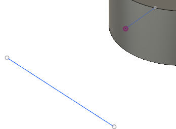
Use the sketch profiles Sketch5 and Sketch6 as rails to create a lofted surface for a single blade.
- In the Browser, confirm that the two line sketches,
 Sketch5 and
  Sketch6 are visible.
- Click
 (Design workspace > Surface tab > Create panel > Loft) to open the Loft dialog.
 - In the canvas, select the two sketch lines as the Profiles, to create the lofted surface for a fan blade.
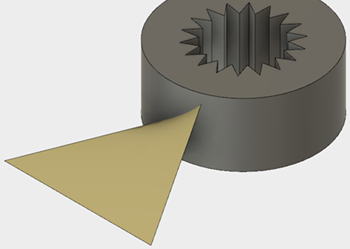
- In the Loft dialog, click OK to apply the tool and close the dialog.
- In the Browser, confirm that the two line sketches,
Trim the outer portion of the blade lofted surface, using the spline sketch, Sketch7, as the Trim Tool.
- In the Browser, click
 next to Sketch7 to make the spline sketch visible.
 - Click
 (Design workspace > Surface tab > Modify panel > Trim) to open the Trim dialog.
 - In the canvas, select the spline, Sketch7, as the Trim Tool.
- Select the outer portion of the lofted surface as the area to remove.
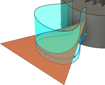
- In the Trim dialog, click OK to apply the tool and close the dialog.
- In the Browser, click
 next to Sketch7 to hide the spline sketch.
- In the Browser, click
Thicken the blade, symmetrically, 0.5 mm on each side.
- Click
 (Design workspace > Surface tab > Create panel > Thicken) to open the Thicken dialog.
 - In the Thicken dialog, set the Direction to
 Symmetric.
 - In the canvas, select the blade as the Face to Thicken.
- Set the Thickness to 0.5 mm.
- In the Thicken dialog, click OK to apply the tool and close the dialog.
- Click
Pattern the blade to create 8 instances around the hub.
- Click
 (Design workspace > Surface tab > Create panel > Pattern > Circular Pattern) to open the Circular Pattern dialog.
 - In the Circular Pattern dialog, set the Pattern Type to Bodies.
- In the canvas, click on the blade to select it as the Object.
- In the Circular Pattern dialog, click
 Select associated with Axis to activate it, then click on the outer cylindrical face to select it as the axis.
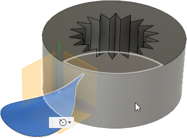
- In the Circular Pattern dialog, set the Quantity to 8
- Click OK to apply the tool and close the dialog.
- Click
Activity 2 summary
In this activity, you started with sketch lines and
- Created a blade lofted surface
- Trimmed the outer edge to form a rounded shape
- Thickened the blade surface to create a solid body
- Patterned the blade solid body to create 8 instances around the hub.