Create component
Tutorial: Create a component
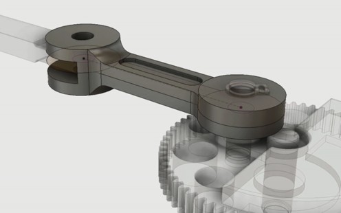
Using the reciprocating saw design provided for this tutorial, you create a connecting rod component to drive the blade assembly.
Open the Reciprocating Saw design
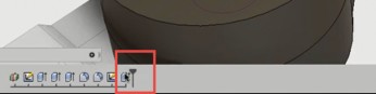
If the Data Panel is not open, click Show Data Panel
 .
.In the Data Panel, open 1_Create Component from Projects > Samples > Workshops & Events > Adoption Path > Mechanical Assembly > 1_Create Component.
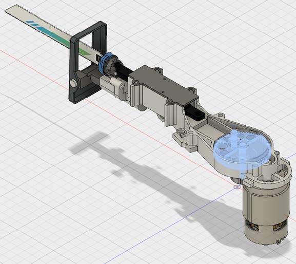
The design appears on the Autodesk Fusion canvas.
Isolate geometry and create a component
Begin by simplifying the model to make it easier to reference components. Use the Isolate command to temporarily hide the geometry that you won't be referencing. From the isolated geometry, create and activate a connecting rod component. This process allows you to capture a timeline for the construction of this component outside the context of the entire assembly.
The connecting rod component will drive the blade holder assembly from the gear and pin assembly.
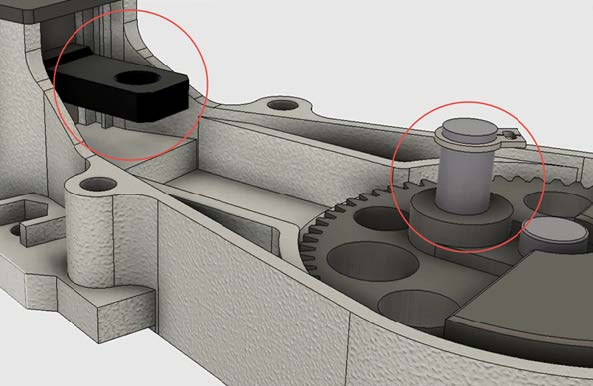
In the browser, Ctrl-click (Windows) or Command-click (macOS) the following:
- Large Spur Gear
- Gear Shaft
- ROD PIN
- Blade Holder Assembly
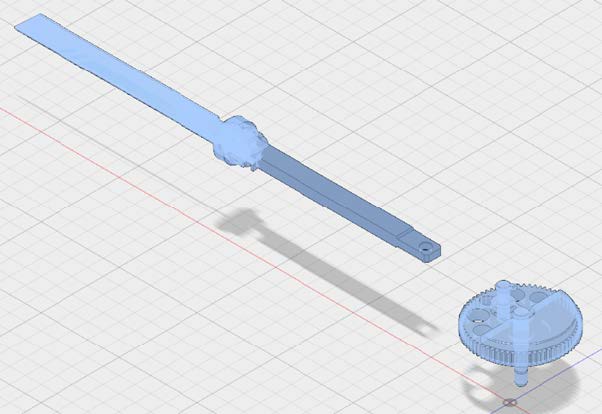
Right-click the selections and choose Isolate. Only the isolated parts are visible.
In the Model workspace, choose Create > New Component.
In the New Component dialog, specify the following values:
- Select Empty Component.
- Set Name to Connecting Rod.
- For Parent, select 1_Create Component in the browser.
- Select Activate.
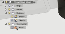
The new connecting rod component appears at the bottom of the browser.
Create a construction plane
Before sketching the new connecting rod, you need a sketch plane. Build a construction plane between the faces of the blade holder assembly that the connecting rod will drive.
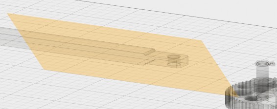
Choose Construct > Midplane.
Select the top face of the blade holder assembly.
Select the bottom face of the blade holder assembly.
A construction plane appears between the two faces.
Begin a sketch on the construction plane
Begin the sketch of the connecting rod by projecting geometry from other components in the assembly. This approach ensures that the new geometry matches the old and creates a parametric relationship between the components and the sketch. If a dimension of a part (such the gear pin) changes, the dimensions of the connecting rod update automatically.
Right-click the construction plane you built and choose Create Sketch from the Marking menu.
Choose Sketch > Project/Include > Project.
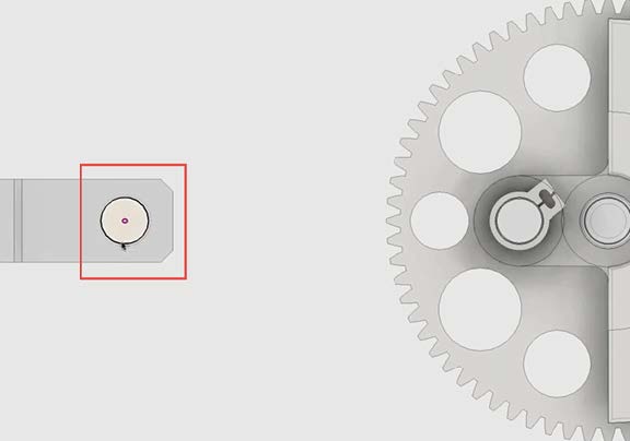
Project the pin in the gear assembly by clicking the circumference of the pin.
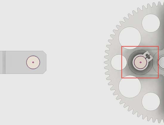
Project the hole in the blade assembly by clicking the circumference of the hole.
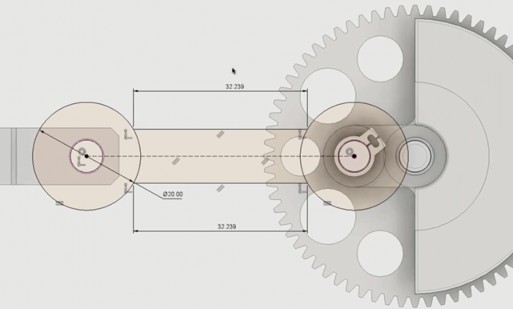
Sketch the ends of the connecting rod
In this step, you use several Fusion techniques to create geometry for the ends of the connecting rod.
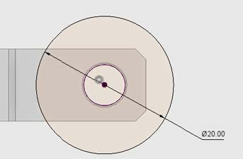
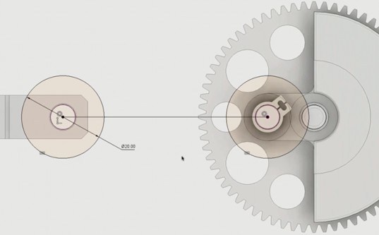
Choose Sketch > Circle > Center Diameter Circle to sketch a circle with a diameter of 20 mm. You can enter the dimension directly or change it later with the dimension tool.
To build a relationship between the circle and the projected hole in the blade assembly, begin by choosing Sketch Palette > Constraints > Concentric. Then click the circle and the projected hole.
The circle and the projected hole now share a center point.
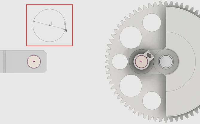
Sketch a circle whose center is aligned with the pin in the gear assembly. The circle can be any size.
Choose Sketch Palette > Constraints > Equal. Then click both circles to make the diameter of the circle on the pin equal to the diameter of the circle on the hole.
Because of this relationship, one circle automatically updates when there's a change to the other circle.
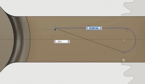
Sketch the center section of the connecting rod
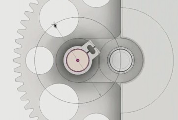
To sketch the center section of the connecting rod, begin by creating a construction line between the center points of the two circles. Then add offsets in both directions to create the edges of the connecting rod.
Finally, trim the extensions of the offset lines inside the two circles.
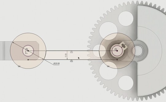
Choose Sketch > Line.
Draw a line between the center points of the two circles.
Choose Sketch > Offset.
Drag the center line down to create a 5 mm offset.
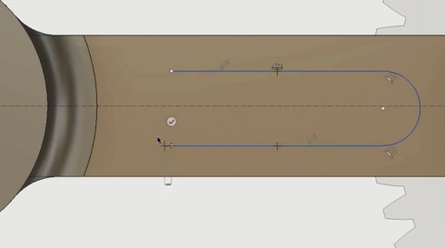
Choose Sketch > Offset again.
Drag the center line up or type -5 mm to create another offset.
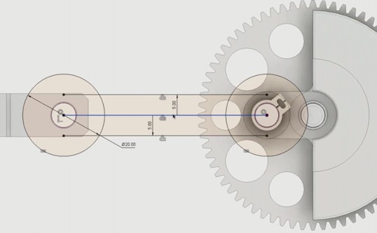
Right-click the center line and choose Sketch > Normal/Construction.
The center line now appears as a dashed line. A dashed line indicates construction geometry, which Fusion ignores.
Choose Sketch > Trim. Then select the ends of the offset lines that extend into the two circles.
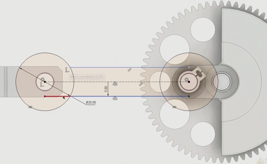
The trimmed lines turn blue, because their dimensions are no longer defined. As a best practice, fully define all sketch geometry before creating 3D components.
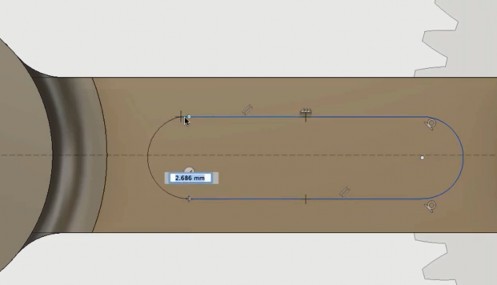
Add dimensions to the trimmed offset lines.
Once you have defined the offset edges with dimensions, the lines appear black.
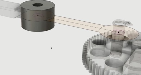
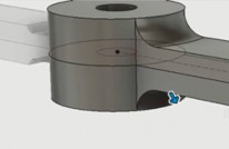
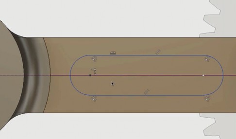
Extrude the ends of the connecting rod
In this step, begin creating a 3D model from your sketch by extruding the circular ends of the connecting rod.
Choose Modify > Press Pull.
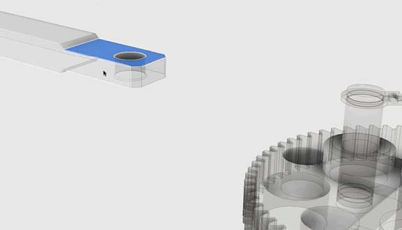
Select the circle around the blade assembly hole.
In the Extrude dialog, specify the following values:
Set Start to Profile Plane.
Set Direction to Symmetric.
Set Distance to 6.5 mm.
Set Taper Angle to 0.0.
Set Operation to New Body.
The circle in the sketch is extruded up and down. When you create 3D geometry from a 2D sketch, the sketch is no longer visible.

To make the sketch reappear, find it under Connecting Rod in the browser, and use the light bulb to control visibility.
Use the ViewCube to reorient the design so that you can see parts to avoid when extruding the other end of the connecting rod.
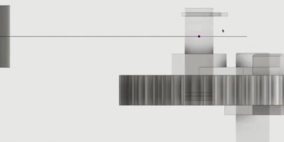
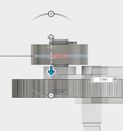
Choose Modify > Press Pull.
Select the edge of the circle around the gear pin for extrusion.
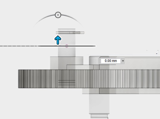
In the Extrude dialog, specify the following values:
- Set Start to Profile Plane.
- Set Direction to Two Sides.
- Set Side 1 Extent to Distance.
- Set Side 1 Distance to 4.00 mm.
- Set Side 2 Extent to Distance.
- Set Side 2 Distance to 3.00 mm.
- Set Operation to New Body.
The two-sided extrusion avoids the center pin on the gear and the small clamp at the top.
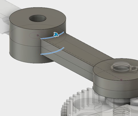
Extrude and fillet the center section
In this step, extrude the center section of the connecting rod and add fillets and chamfers.
Choose Create > Extrude.
Select the face of the center section of the connecting rod.
In the Extrude dialog, specify the following values:
- Set Start to Profile Plane.
- Set Direction to Symmetric.
- Set Distance to 3 mm.
- Set Operation to Join.
The center section extrudes equally up and down.
Right-click to display the Marking menu, and select Press Pull.
Tip: The last command used (in this case, Extrude) is always shown at the top of the Marking menu.Select the top and bottom edges of the connecting rod center near the blade assembly.
Press Pull automatically provides fillet options.
In the Fillet dialog, specify the following values:
Set Edges to 2 Selected.
Set Type to Constant Radius.
Set Radius to 3.50 mm.
Select Tangent Chain.
Rotate to the other side of the connecting rod.
Hold down the Ctrl key (Windows) or Command key (macOS). From a list of edges, select the top horizontal edge and the two vertical edges of the connecting rod near the gear assembly.
In the Fillet dialog, specify the following values:
- Set Type to Constant Radius.
- Set Radius to 3.50 mm.
- Select Tangent Chain.
Click OK to end the Press Pull command.
Tip: To add more edges to a fillet, hold down the Ctrl key (Windows) or Command key (macOS). Then remove previewed fillets and add more edges. This technique also works for profiles with extrusions.
Place a slot on the top face of the connecting rod
In this step, you learn Fusion techniques for sketching and extruding a slot on the top-center face of the connecting rod.
Choose Sketch > Create Sketch. Then select the top face of the center section of the connecting rod.
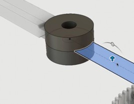
Choose Sketch > Line.
To sketch the slot as a continuous profile, draw a horizontal line and then click and hold at the endpoint to switch to the arc tool.
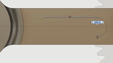
While still in the line command, hover over the beginning point of the upper edge. The lower edge of the profile moves up to the beginning point of the upper edge.
This step and the next create sketch constraints through extension lines.
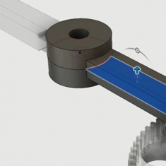
While still in the line command, bring the lower edge down until it is parallel with the upper edge and the two endpoints are vertically aligned.
Click and hold to draw an arc to complete the slot profile.
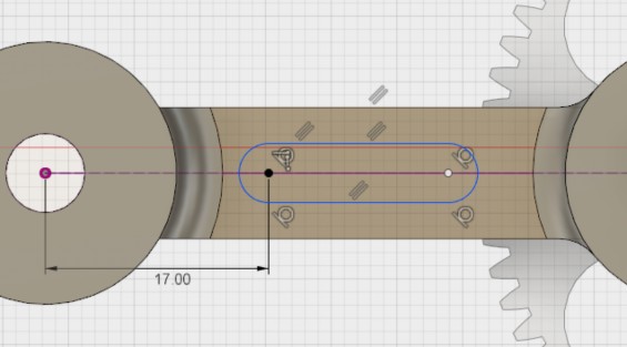
Choose Sketch Palette > Constraints > Coincident. Then select both the center of the arc and the construction line to center the slot.
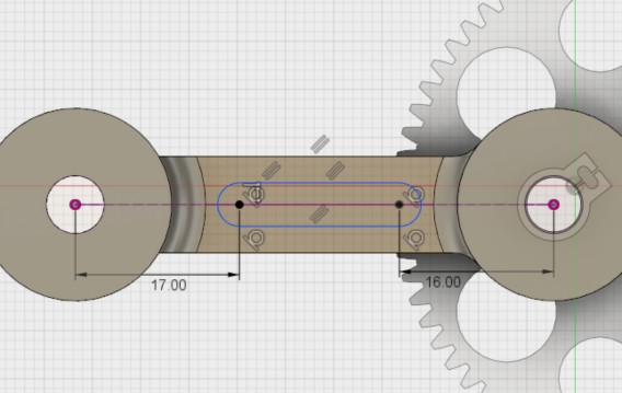
Add a dimension of 17 mm to locate the slot at the blade assembly end of the rod.
Add a dimension of 16 mm to locate the slot at the gear assembly end of the rod.
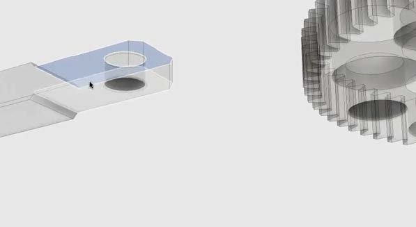
Right-click and select Press Pull.
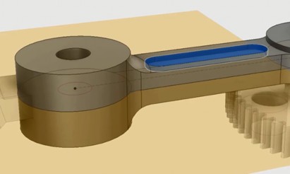
Select the lower and upper halves of the profile to extrude the slot.
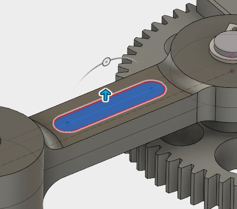
In the Extrude dialog, specify the following values:
- Set Start to Profile Plane.
- Set Direction to One Side.
- Set Extent to Distance.
- Set Distance to -1.00 mm.
- Set Operation to Cut.
The slot is cut into the connecting rod.
Mirror the slot on the bottom face of the connecting rod
Instead of sketching a slot profile on the bottom face of the connecting rod, use the slot feature you already created for the top face. Select it in the timeline and use the Mirror tool to duplicate the feature on the bottom face.
Choose Create > Mirror.
In the Mirror dialog, set Pattern Type to Features.
For Objects, select the existing slot feature from the timeline.
For Mirror Plane, select your construction plane in the browser.
The construction plane being mirrored becomes visible.
In the Mirror dialog, click OK.
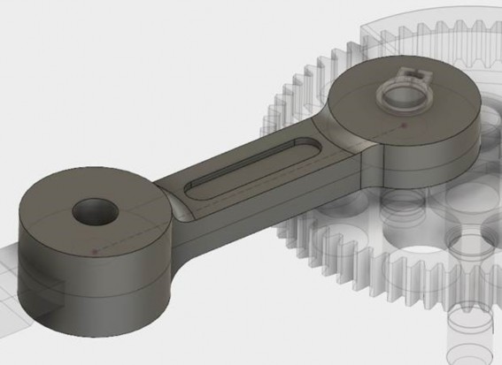
The bottom slot is cut into the connecting rod.
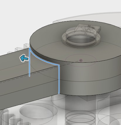
Remove material from the rod to connect the blade assembly
In this final step, remove material from an end of the connecting rod to connect it to the blade assembly.
Using the ViewCube, reorient the model to Front, zooming in on the view where the blade assembly meets the end of the connecting rod.
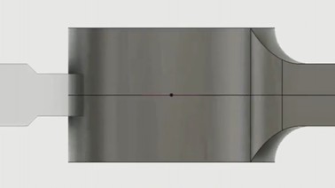
Choose Sketch > Create Sketch.
Select the side of the blade assembly.
Right-click and choose Sketch > Project.
Select the blade assembly to project the geometry.
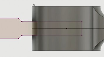
Right-click and choose Sketch > Offset.
Select the blade assembly profile.
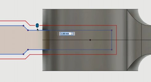
In the Offset dialog, specify the following values:
Select Chain Selection.
Set Offset position to 1.00 mm. Upper and lower offsets of 1.00 mm appear in red.
Right-click, choose Press Pull, and select the profiles to be cut away.
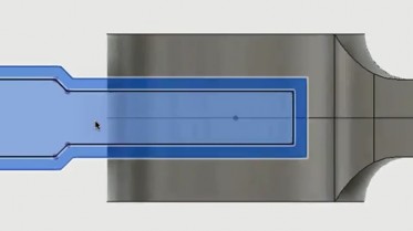
In the Extrude dialog, specify the following values:
Set Start to Profile Plane.
Set Direction to Symmetric.
Set Distance to -30 mm.
Set Operation to Cut.
Under Objects to Cut, deselect everything except Connecting Rod.
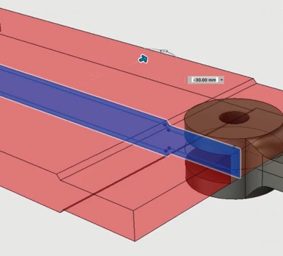
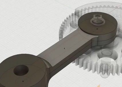
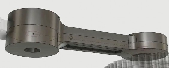
The material is removed from the end of the connecting rod.
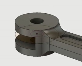
You can view the connecting rod attached to the blade assembly and the gear assembly.