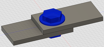
Bolt Connector
A bolt connector adds a bolt to your model without having to model it. You can add a threaded hole and a nut to the bolt connection.
Click
 (Simulation workspace > Setup tab > Constraints panel > Bolt Connector).
Select the Location for Bolt Head. Click a circular edge at the end of a hole where you want the bolt head to be located. The axis of the bolt runs through the centroid of the circular edge, and the bolt axis is normal to the plane of the circular edge.
Choose the Bolt Subtype. Available options are With Nut or Threaded Hole.
Select the Location for Nut or Location for Threads depending on your selection for the Bolt Subtype. The nut location can be either an edge, or a face, that is parallel to the plane of the edge circle used to define the bolt location. The selection requirements are as follows:
The nut location can be an edge, or a face, that is perpendicular to the bolt axis.
If the nut location is a face, the face must contain a hole that is concentric with the bolt axis.
The thread location must be a cylindrical face that is concentric with the bolt axis.
The software prevents you from selecting an invalid face for either of these parameters.
Optional: For the Threaded Hole option, you can adjust the Usable Thread Length of the bolt. For the With Nut option, the bolt length is determined automatically and cannot be altered.
Optionally, add a Head Washer, a Nut Washer, or both. You can adjust the Height of each washer independently.
Note: Currently, you cannot specify the diameter of a washer. Also, a head washer or nut washer only increases the length of the bolt according to the washer height you specify. A washer does not affect the area of contact between the head or nut and their contact faces. In other words, a washer does not reduce local contact stresses by spreading the bolt load over a larger area. While the visualization of the bolt suggests this effect, the actual calculations do not consider the effect.Optionally, specify a bolt pre-load. Choose between the following two Pre-load Type options:
Axial: Specify the axial preload force in the Pre-load Value field.
Torque: Specify the bolt tightening torque in the Pre-load Value field and also the friction coefficient in the Torque Coefficient field. The program converts these values to an equivalent axial pre-load force.
Note: Click Change Units to choose alternative units for the pre-load parameters.
Optionally, click the current assigned material shown to the right of the Material Properties heading. You can view the properties or choose a different material from the library. Alternatively, activate the User Defined option and specify the Elastic Modulus, Poisson's Ratio, and Thermal Expansion Coefficient of the bolt manually.
Click OK.
 Note: While using a bolt connector it is important to manually update contacts. By default the automatically applied contact is Bonded, in most cases the contact between bodies held together by bolts should be Separation.