Add a rigid body connector
You can use a rigid body connector in the following studies:
| Study icon | Study Name |
|---|---|
 |
Static Stress |
 |
Modal Frequencies |
 |
Structural Buckling |
 |
Nonlinear Static Stress |
 |
Quasi-static Event Simulation |
 |
Dynamic Event Simulation |
Click
 (Simulation workspace > Setup tab > Constraints panel > Rigid Body Connector).
Select the Subtype. Available options are:
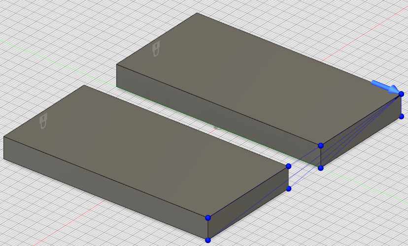
Rigid Body: Fully rigid connection. When using this type of connector, the Dependent Entities move exactly how the Anchor Point (independent entity) moves.
Interpolation: When using this type of connector, the displacement of the Reference Point is the weighted average of the displacements of the Entities to Average.
Important*: You must apply Interpolation rigid connectors carefully. Improper creation of this type of connector can cause fatal errors when solving.
Select the Anchor Point or Reference Point, depending on your selection for the Subtype.
Select the Dependent Entities or Entities to Average, depending on your selection for the Subtype.
Choose the degrees of freedom to fix. Available options are Ux, Uy, and Uz, which correspond to X, Y, and Z translation, respectively.
Note: When connected to solid bodies, rotation at the points of attachment is not limited by rigid connectors. For example, if a rigid connector is attached to a straight edge of a solid body, the body is free to rotate about that edge. A straight line of mesh points without torsional rigidity constitutes a hinge.Click OK.
