Air traps result
The Air traps result shows how severe air traps will be and where they are likely to occur on the model.
Air traps
An air trap occurs where the melt traps and compresses a bubble of air or gas between two or more converging flow fronts, or between the flow front and the cavity wall. Typically, the result is a small hole or a blemish on the surface of the part. In extreme cases, the compression increases the temperature to a level that causes the plastic to degrade or burn.
Air traps are often due to converging flow fronts caused by racetrack or hesitation effects, or by non-uniform or non-linear fill patterns. Even when the part has balanced flow paths, inadequate venting can cause air traps to occur at the ends of flow paths.
Things to look for
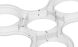
In the Air traps result, air traps appear as colored marks on a transparent model. Note the location of the air traps, and where the appear relative to the injection locations and other features of the model. Air traps can reveal the following problems in your part:
- Burn marks caused by air in an air trap, which ignites under pressure and burns the plastic.
- Short shots caused by the incomplete filling of the part, or bubbles of air or gas in the plastic part.
- Other surface blemishes caused by air traps.
Using this result
Use the Fill animation result, in conjunction with the Air traps result to check the filling pattern and assess the likelihood of air traps appearing. If the flow paths are not balanced, try to balance them. Note the location of the air traps and see if you can move them to a location that is easier to vent.
Next steps
The following methods can be used to prevent air traps:
- Add flow leaders or deflectors to your simulation model.
- Increase the injection speed to eliminate air traps caused by converging flow fronts and hesitation.
- Decrease the injection speed to reduce air traps caused by poor venting, and to prevent burn marks.
- Decrease the part wall thickness ratio to reduce racetracking.
- Move the injection locations so that the air traps form in areas that are easy to vent, such as the parting plane.