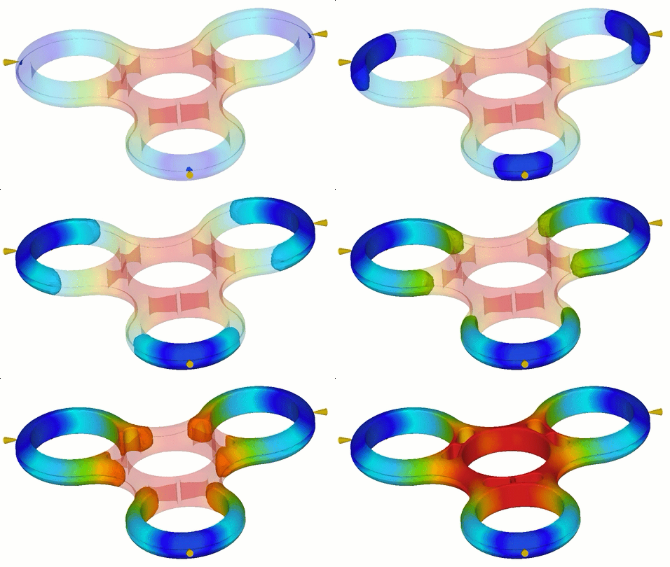
Fill animation result
The Fill Animation result shows the position of the flow front at regular intervals as the cavity fills.

Flow pattern
Ideally, injection locations should be placed so that all flow paths within a mold fill at the same time. In addition, where possible, the filling pattern in the cavity should be unidirectional, that is, it should not change direction during the filling phase.
The illustrations above show the contour colors that represent the flow of plastic into the part. Regions that fill in the same time as other regions are represented by same color. In illustration 1. the extremeties of the cavity are not all filled at the same time. Illustration 2. shows how the injection location can be moved to fix this.
Things to look for
The Fill animation result is ideal for checking for a variety of fill patterns that can predict how well a cavity will fill.
- Short shot: On the Fill animation result, a short shot appears as translucent. Check the ends of the flow paths for any translucent areas.
- Hesitation: If a Fill animation result shows a section where the contours are very closely spaced, hesitation may have occurred. Hesitation can cause a short shot if a thin section freezes off before the part is completely filled.
- Overpacking: If a Fill animation result shows that one flow path finishes before others do, it may indicate overpacking. Overpacking can cause high part weight, warpage, and non-uniform density distribution throughout the part.
- Weld lines: Compare the Fill animation and Weld lines results to confirm their presence. Weld lines can cause structural and visual defects.
- Air traps: Compare the Fill animation and Air traps results to confirm their presence. Air traps can cause structural and visual defects.
Using this result
The fill animation result uses dark blue to represent the first areas to fill, and finishes with red to represent the last areas to fill. If the part is a short shot, the section that did not fill has no color. In a part with a good fill time result the flow pattern is balanced, which means the following:
- All flow paths finish at the same time and reach the edges of the model simultaneously. In the previous diagram, each flow path should end with red contours.
- The contours are evenly spaced and indicate the speed at which the polymer is flowing. Widely-spaced contours indicate rapid flow; narrow contours indicate that the part is filling slowly.
Next steps
The following methods can be used to improve the fill pattern:
- Add flow leaders or deflectors to your simulation model to fix hesitation.
- Move the injection location so that all flow paths fill at the same time.
- Add injection locations to balance the flow paths.
- Decrease the injection time to increase the melt temperature and resolve short shots and difficult to fill areas.

