Mesh quality
When critiquing the suitability of a mesh, consider the following characteristics:
- Element order: Two different element order settings are available in Fusion:
- Linear: Linear elements have nodes at the corners only, and they have straight edges. A linear tetrahedral element has four triangular faces, six edges, and four nodes.
- Parabolic: Parabolic elements have corner nodes and an extra node at the midpoint of each edge. A parabolic tetrahedral element has ten nodes (four corner nodes and six midedge nodes).
- Curved mesh elements: This enhancement is only possible for parabolic elements. When enabled, elements located along curved faces have curved edges. This capability places the midedge nodes on the actual surface of the curved face. In other words, the middle nodes do not have to lie on a straight line that connects the corner nodes. Curved mesh elements conform more accurately along curved geometry and therefore enhance the simulation accuracy.
- Aspect ratio: There are several different ways to define and calculate the aspect ratio of an element. The simplest method is to divide the longest edge length by the shortest one. An ideal element has an aspect ratio of 1.0. Elements with aspect ratios exceeding 10 should be avoided in critical stress regions and also limited to a small percentage of the total volume. Sometimes, particularly for complex geometry, aspect ratios of up to 40 are not uncommon. As long as these poorer quality elements are not located in critical stress regions, they may be tolerable.
If you specify a large element size for a model with relatively small features, high aspect ratio elements are generated along the small features. Short edges are required to conform to the small features, but other edges are long due to the specified element size. Similarly, a thin part with a large surface mesh size contains high aspect ratio solid elements. In such cases, you can reduce the element size globally or locally to improve the aspect ratios.
- Adjacent mesh size ratio: A measure of the transition rate between small elements in a localized region and the larger global size. Most meshing routines, including the one in Fusion, automatically perform a gradual transition between small and large elements.
- Number of elements through the thickness: There is a rule of thumb that parts subjected to flexural (bending) stresses should have a minimum of four elements through the thickness of the part. This rule applies to linear elements. The multiple elements are required to reasonably represent the varying and reversing tensile stress magnitude through the thickness. When using parabolic elements, two elements through the thickness produce similar results (due to the additional nodes between the corner vertices).
For thin parts, it is often difficult to achieve a mesh that is dense enough to satisfy this guideline. You can use local mesh refinement to reduce the element size only in critical regions. In this way, you can achieve the recommended number of elements without producing an extreme total element count.
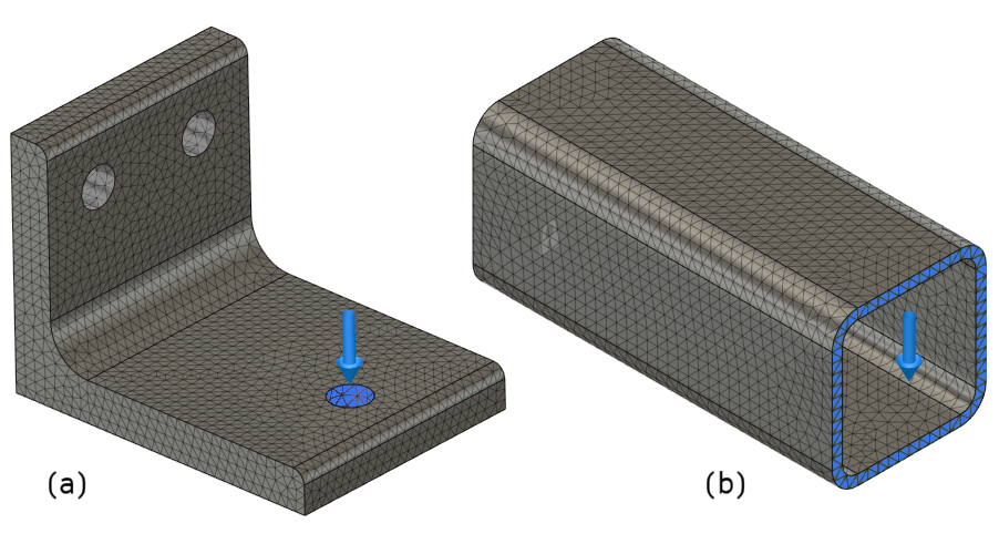
Not all thin parts require multiple elements through the thickness for acceptable accuracy. If the stress is mostly tensile or compressive membrane stresses (not bending stresses) one element through the thickness may be adequate. Consider the following comparison:

Figure 1: When are multiple elements needed through the thickness of a part?
Both parts are fixed at the left end and have a downward force applied, which produces bending. In the horizontal portion of the angle, Part (a), the tensile stress reverses through the thickness of the part. The top surface is in tension, and the bottom surface is in compression. For such cases, a minimum of four linear or two parabolic elements is needed through the thickness to adequately capture the stress gradient.
In Part (b), the top and bottom walls of the square tube experience only a slight change in tensile stress magnitude through the thickness. The top wall is in tension, and the bottom wall is in compression. For the elements along the two side walls, the stress gradually changes from tensile to compressive as you move from top to bottom. In such cases, a single linear element through the thickness is sufficient. The stress gradient through the thickness is minimal, and there is no stress reversal.