| File/s needed: |
| Click to download the Advanced [US Units] tutorial model files. |
- Launch InfoDrainage and select Open Existing from the Welcome Screen. Choose the file ID_US_Advanced_Tutorial_Ch1.iddx
- The model starts with one Phase representing the Existing site conditions.

-
All background data (image, surface and CAD file) for both Phases have already been loaded. In order to load any of these items, right-click the appropriate layer from the Tree View and select Import Data.
Note: Note that this step can be ignored in terms of the tutorial though is mentioned for user reference.
- In developing this site, we know we are going to increase the runoff flow and volume. Therefore, we will need to design storage to handle the increase in stormwater. We are going to be using green infrastructure techniques to slow down and hold back the water. First, we are going to define the contributing area or catchment that we are draining in this example so that we can calculate the existing flow conditions. Before you draw the Inflow Area catchment extents, go to the Plan ribbon and select the Snap option to ensure that the vertices can exactly match the CAD file layout. Selected options/functions will be highlighted.

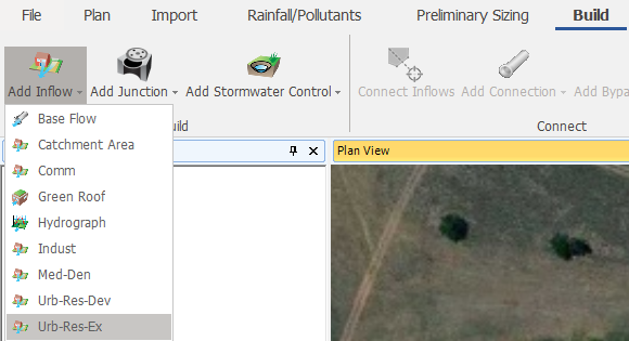
- Under the Build ribbon, select the Add Inflow option, and then select Urb-Res-Ex Inflow Area template from the drop-down list.

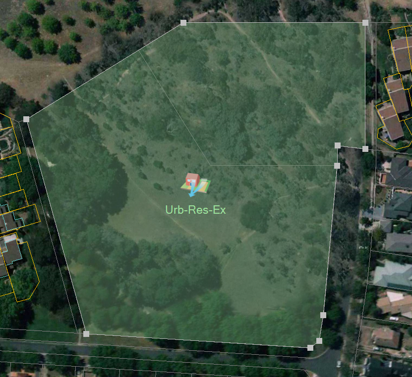
- You can now use the left mouse button to draw the Inflow extents by snapping along the CAD layout background, as shown below. When you are done drawing the polygon, use the right mouse button to end the drawing action. Press
Esc to exit the drawing mode.

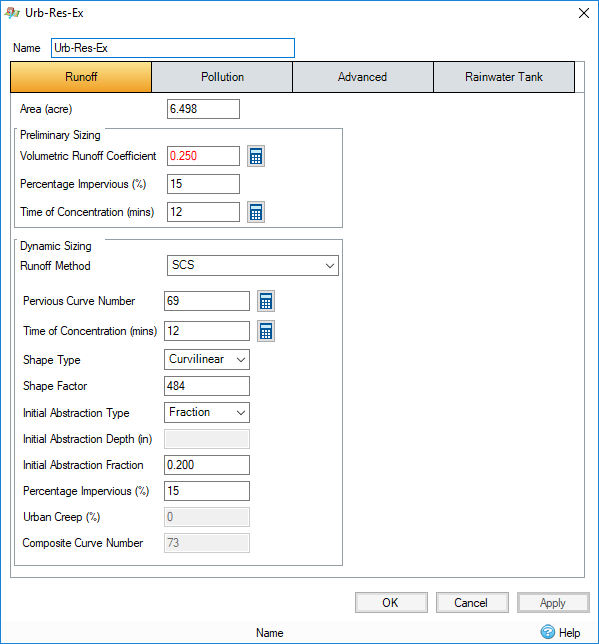
- Double-click anywhere within the polygon to open the Inflow Area form (or right-click and select Edit). You will see the tabbed options for entering data. The Area is automatically calculated based on the Inflow Area polygon that was traced over the scaled CAD background image file. Since the Urb-Res-Ex template was used, all the data in the tabs are filled in based on values defined within that template. Notice there are Preliminary Sizing and Dynamic Sizing input sections - the Preliminary Sizing section is for generating the 'static' inflow Rational method (Q = C*I*A) rates and is exclusively used for Preliminary Pipe Design. The Dynamic Sizing section
is what will be used for the full hydrograph hydraulic analysis, which will be performed as part of this tutorial and is most commonly used on design assessments. Click OK to close the dialog.
